Guralp Systems CMG-DCM build <10,000 User Manual
Page 191
Operator's Guide
and correspond to similarly labelled connectors on a standard CMG-
DM24. The illustration shows a four-channel unit; the seven-channel
unit has an additional connector for sensor B.
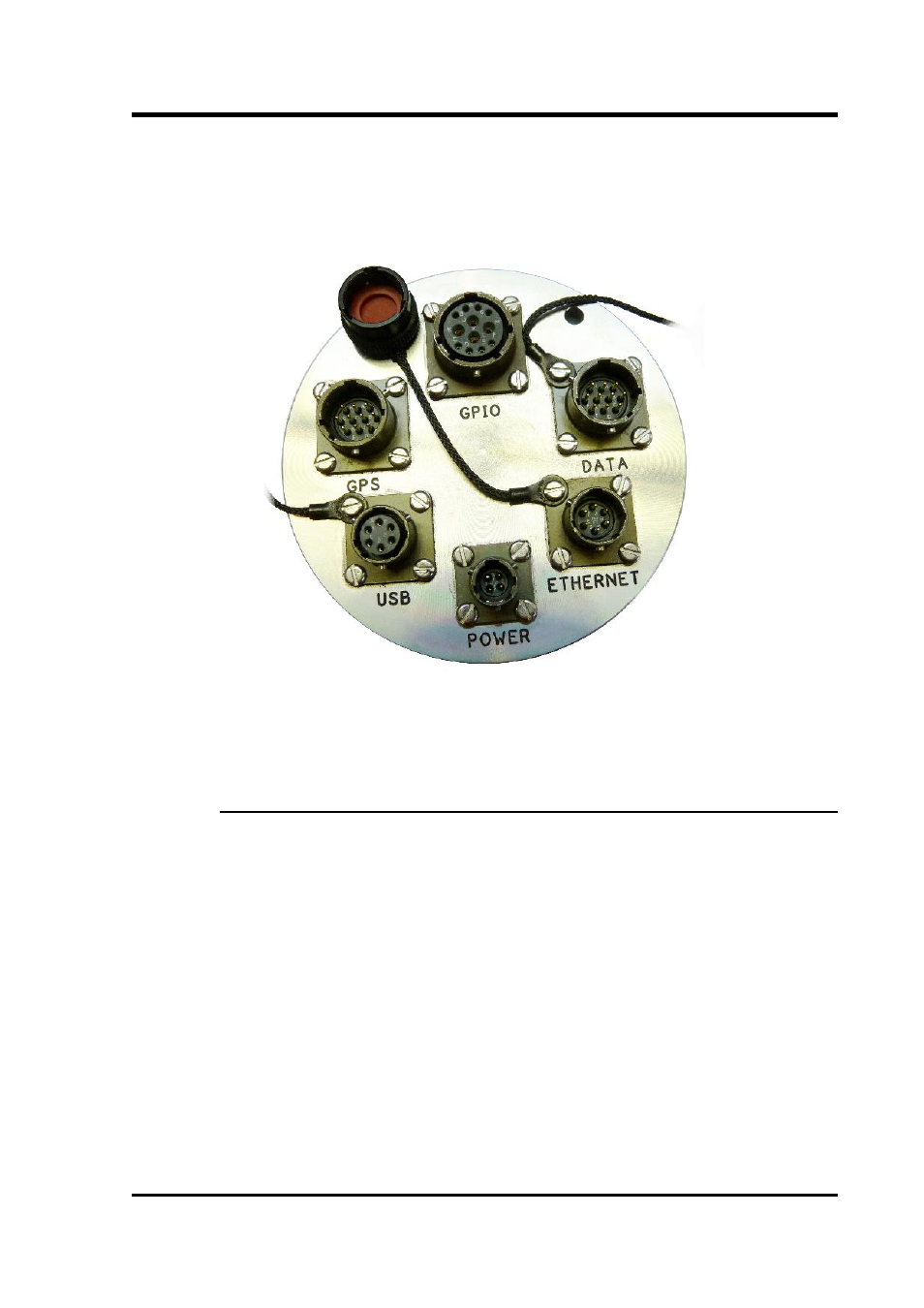
The digital connectors are arranged at the other end of the cylinder:
The pin-outs for each of these connectors are given in sections 14.3.6
through to 14.3.10.
14.2.1 Internal Connections
Internally, the digitiser module and acquisition module are connected
using three serial lines. The exact connections depend on the
synchronisation mode, determined by the service running on Port C of
the acquisition module.
In all cases, the GCF data output from the digitiser module is
connected to Port A of the acquisition module, which should be set to
“GCF in” at 38,400 Baud. It is currently possible to set the Baud rate of
the digitiser's data output port and of the EAM's Port A independently,
leading to a loss of data communication between the two modules if
the two do not match. If you wish to have a higher transfer rate
between the two modules, both ends must have their Baud rates
increased separately.
November 2010
191