2 j2 | redundancy connector, db-9f, 3 j3 | remote connector, db-9m – Comtech EF Data CDM-760 User Manual
Page 55
Rear Panel Connections
Revision 2
CDM-760 Advanced High-Speed Trunking Modem
MN-CDM760
3–7
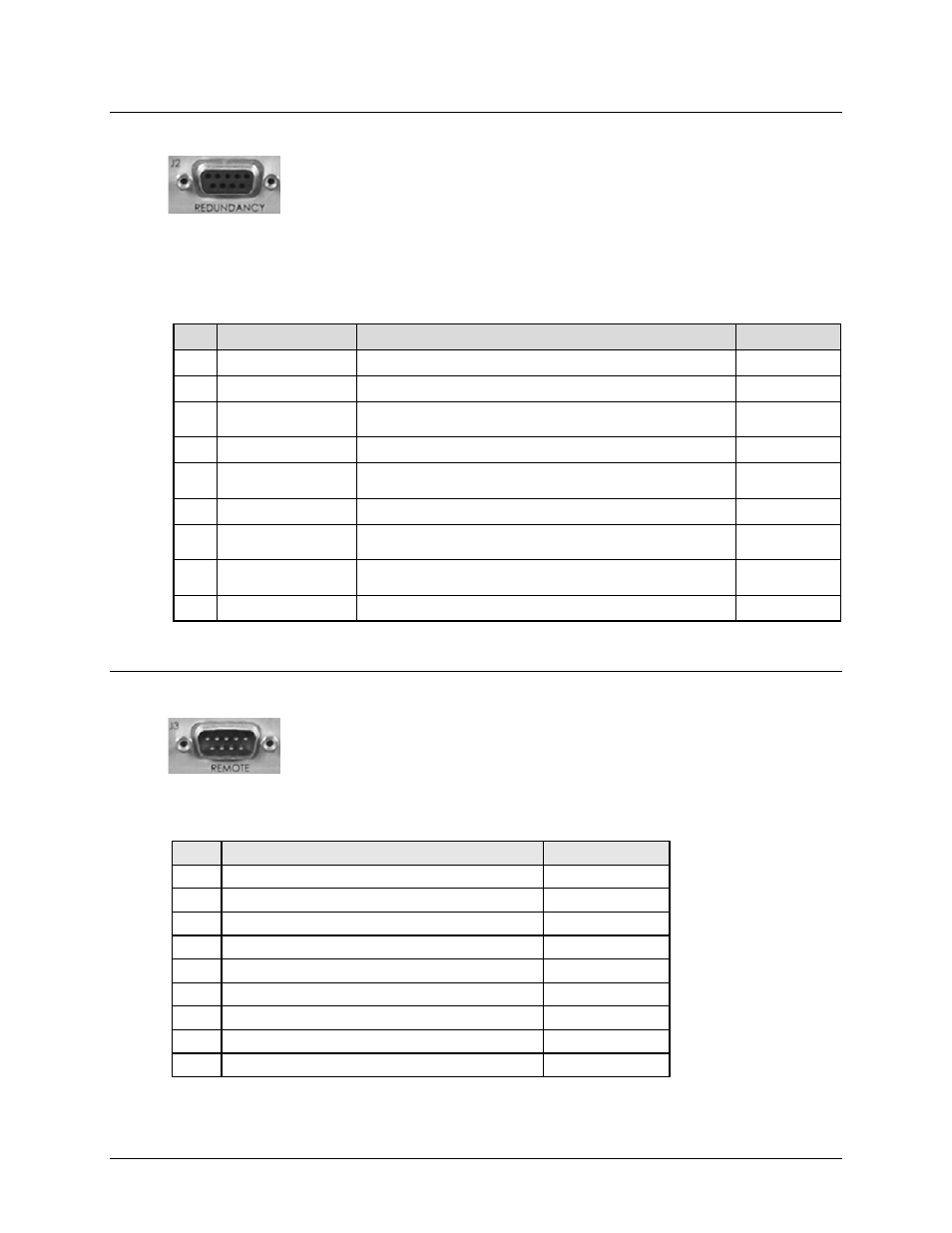
3.2.2.2 J2 | REDUNDANCY Connector, DB-9F
The J2 | REDUNDANCY 9-pin Type ‘D’ female (DB-9F) connector provides the
1:1 control interface. It provides serial communications to transfer
configuration information from the Primary to the Backup modem, and a
Fault/Clock signal to signal the switch when a fault occurs. It is intended only for connection to a
CRS-170A or CRS-180 1:1 Redundancy Switch.
The connector pinouts are as follows:
Pin # Name
Signal Function
Signal Type
5 MDM_COM_OUT_ENA Enable “Mdm_Comm_Out” signal
LVTTL Output
9
12VOLT_OUT
+12 Volts at 300 ma
12V 300 ma
4 ONLINE
Commands modem to be Online/Offline
(Use pull-up on Modem side input)
LVTTL Input
8
SER_DATA
Fault Serial Data Signal from modem
LVTTL Output
3 TX_IF_MUTE_B
Capability to mute modem’s Tx IF (Low=Mute)
(Use pull-up on Modem side input)
LVTTL Input
7
SER_CLK
Fault Serial Clock Signal 64KHz
LVTTL Output
2 MDM_COM_IN
UART comm to modem from controller
(9600 to115.2BUAD)
LVTTL Input
6
MDM_COM_OUT
UART comm. from modem to controller
(9600 to115.2BUAD)
LVTTL Output
1 GND
Chassis Ground
Gnd
3.2.2.3 J3 | REMOTE Connector, DB-9M
The J3 | REMOTE 9-pin Type ‘D’ male (DB-9M) connector provides the remote
control interface via an M&C computer or terminal device. It is user selectable
for either EIA-232 or EIA-485.
The connector pinouts are as follows:
Pin #
Description
Direction (I/O)
1 Ground
–
6
EIA-485 Receive Data B *
I
2 EIA-232 Transmit Data
O
7
EIA-485 Receive Data A *
I
3 EIA-232 Receive Data
I
8
EIA-485 Transmit Data B
O
4 Reserved - do not connect to this pin
–
9
EIA-485 Transmit Data A
O
5 Ground
–
* Use for 2-wire EIA-485 operation