2 cdm-760 cabling connections – Comtech EF Data CDM-760 User Manual
Page 52
Rear Panel Connections
Revision 2
CDM-760 Advanced High-Speed Trunking Modem
MN-CDM760
3–4
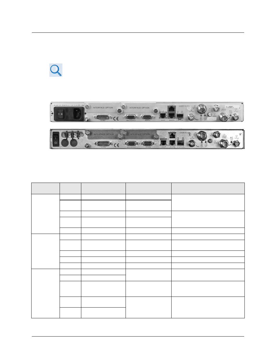
3.2 CDM-760 Cabling Connections
The rear panel connectors (Figure 3-3) provide all necessary external connections between the
unit and other equipment.
•
For full information about the optional PIICs (Plug-In Interface Cards) and
their traffic data interface connectors, see Appendix C. PIIC OPTIONS.
•
For full information about the optional High-Speed Packet Processor and its
management and traffic data interface connectors, see Appendix F.
OPTIONAL HIGH-SPEED PACKET PROCESSOR.
(TOP) Standard AC Unit
(BOTTOM) Optional 48V DC Unit
(FUTURE)
Figure 3-3. CDM-760 Cabling Connections
Table 3-1. CDM-760 Rear Panel Connectors
Group Name
(See Sect.)
Ref Des Name
Connector Type
Function
J9
L-BAND RX IN
Type ’N’ female
IF Input
J11
IF RX IN
BNC female
(70/140MHz band)
J12
L-BAND TX OUT
Type ’N’ female
IF Output
J13
IF TX OUT
BNC female
(70/140MHz band)
J10
TX MON
Type ’SMA’ female
Monitor L-Band Output
J1
ALARM
15-pin Type ‘D’ male
Form C Alarms (relay closures)
J2
REDUNDANCY
9-pin Type ‘D’ female
Connection to External 1:1
Redundancy Switch
J3
REMOTE
9-pin Type ‘D’ male
Serial Remote Interface (EIA-485/232)
J4
MGMT
RJ-45 female
10/100/1000 BaseT M&C
J8
EXT REF
BNC female
External Reference Input / Output
J5
DATA (GBEI1)
RJ-45 female
10/100/1000 BaseT Gigabit Ethernet
traffic
J6
DATA (GBEI2)
J7
OPTICAL
SFP (Small Form
Factor Pluggable)
Module cage
Accepts optional hot-pluggable SFP
1000Base-SX 850mm Transceiver
Module
N/A
INTERFACE OPTION
SLOT 1
PIIC (Plug-In Interface
Card) slots
Accepts optional data interface
modules (e.g., G.703 E3/T3/STS-1,
OC-3 Single / Multi Mode. STM-1
Copper, etc.)
N/A
INTERFACE OPTION
SLOT 2