Comtech EF Data CDM-760 User Manual
Page 120
Front Panel Operation
Revision 2
CDM-760 Advanced High-Speed Trunking Modem
MN-CDM760
6–34
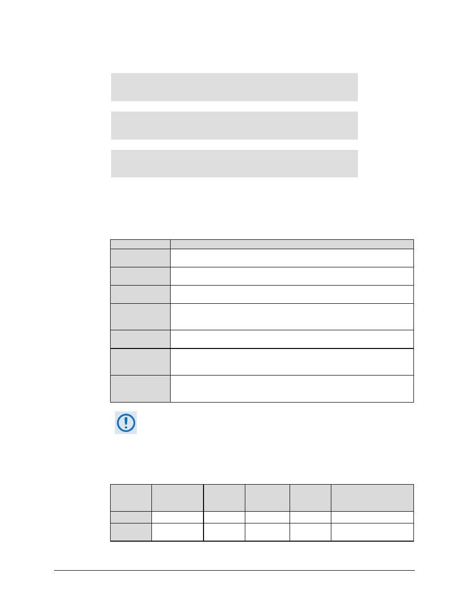
(CONFIG: INTF) (PIICX=G703) Mask
Mask: TxPll:Fault
InpSigLoss:Alarm more…. ()
Mask: ExtClkAct:Fault
ExtClkInRange:Alarm more…. ()
Mask: RxPLL:Fault RxOF:Fault
RxUF:Alarm
()
These menus set how the modem reports interface alarm or fault states. Use the
arrow keys to select TxPll, InpSigLoss, or more... to go to the next screens. There, use
the arrow keys to select ExtClkAct, ExtClkInRange, RxPll, RxOF, or RxUF. Press
ENTER. Note the following:
Selection (Alarm) Description
TxPLL
The Tx Clock PLL is high or low, meaning that the Tx Clock Source is significantly
different than the rate of the transmitted data.
InpSigLoss
Input Signal Loss means that the PIIC G.703 interface TX-IN connector finds no
traffic.
ExtClkAct
External Clock Activity means that the External Clock is selected by either the
TxClock or RxClock, but no clock is present on J8 | EXT REF.
ExtClkInRange
External Clock In Range means that the External Clock is set by the TxClock or
RxClock, but the rate of the clock on J8 | EXT REF does not agree with the rate
expected by the modem.
RxPLL
The Rx Clock PLL is railed high or low, meaning that the Rx Clock Source is
significantly different than the rate of incoming data.
RxOF
Rx Overflow means that the demodulator traffic is too fast for the RxClock clock
setting. This causes the buffer to overflow and to re-center, losing data in the
process.
RxUF
Rx Underflow means that the demodulator traffic is too slow for the clock RxClock
setting. This causes the buffer to underflow and to re-center, losing data in the
process.
If ExtClkAct IS NOT in an Alarm or Fault condition but the ExtClkInRange IS
in Alarm or Fault condition, this means that the clock source rate and the
modem’s programmed External Clock rate are different.
Use the arrow keys to set the report state for each selection as Alarm, Fault,
Mask, or Fault-Tx On. (The RxPll, RxOF, and RxUF selections provide only Alarm, Fault,
and Mask.) Press ENTER. Note the following:
Mask State
Front Panel
LED ‘UNIT
STATUS’ Color
Fault State
Causes
Redundancy
Switch
Mutes
Tx Carrier
Front Panel VFD
Visible Location
Alarm
Amber
None
No
No
Monitor: Live Alarms menu
Fault
Red
J1 Alarm
Connector
Yes
Yes
Monitor: Stored-Events Log