Comtech EF Data CDM-760 User Manual
Page 312

Appendix E
Revision 2
CDM-760 Advanced High-Speed Trunking Modem
MN-CDM760
E–2
•
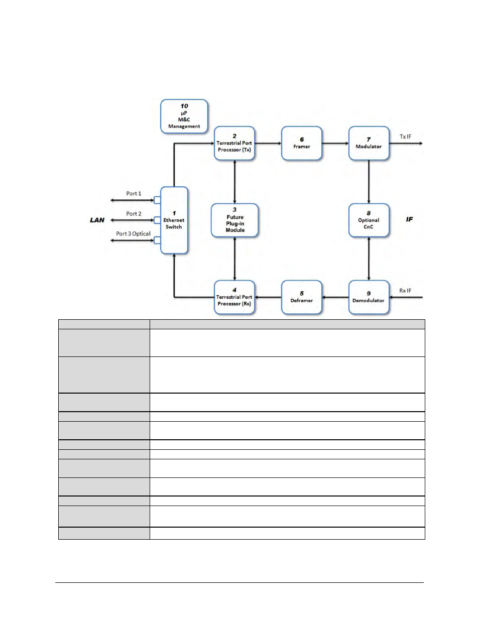
The arrows in the diagram indicate the direction of data flow; while data flow between Blocks
1 and 2 is valid, data flow between Blocks 2 and 1 does not occur. Arrows on both ends of a
link show where data flow is bidirectional.
Name
Function
LAN Region
This unmarked region of the diagram refers to the LAN – the source / destination for data traffic.
The information of interest is tailored to Ethernet interfaces, so most of the statistics do not apply
to the G.703 interface.
Block 1 – Ethernet Switch
The LAN’s access to the modem is at the Ethernet switch. There are two RJ-45
10/100/1000BaseT ports (Port 1 – J5 | DATA / GBEI1, and Port 2 – J6 | DATA / GBEI2) and one
optional optical Gigabit Ethernet (SFP module) port (Port 3 – J7 | OPTICAL) available at the rear
of the modem.
Block 2 – Terrestrial Port
Processor (Tx)
Data from the LAN destined to the satellite flows into this block.
Block 3 – Expansion Slot
This is reserved for future plug-in modules.
Block 4 – Terrestrial Port
Processor (Rx)
This is the counterpart to the Tx processor. It forms Ethernet packets and forwards them to the
Ethernet Switch.
Block 5 – Deframer
The data from the satellite frames is recovered.
Block 6 – Framer
Data processing to assemble data into frames for the modulator is performed in this block.
Block 7 – Modulator
Frames are mapped into the appropriate FECFrame and mapped into the selected ModCod for
transmission to the satellite.
Block 8 – CnC
Signals to and from the satellite are processed here to cancel the locally transmitted carrier and
receive the carrier from the distant end.
Block 9 – Demodulator
Carriers received from the satellite are processed here to recover data frames.
Block 10 – µP / M&C /
Management
The microcontroller (µP) is involved in collection and calculation of statistics.
IF Region
This unmarked region of the diagram refers to data to or from the satellite link.
Figure E-1. CDM-760 Data Flow Diagram
