Comtech EF Data CDM-760 User Manual
Page 321
Appendix F
Revision 2
CDM-760 Advanced High-Speed Trunking Modem
MN-CDM760
F–7
Step
Task
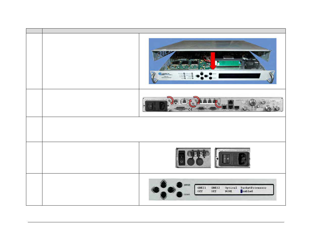
7
Use the screwdriver and existing fasteners to reinstall
the top cover onto the CDM-760 chassis.
IMPORTANT: You must reinstall the cover after
installing the High-Speed Packet Processor Card Option
Kit. It is critical that you operate the modem with the
cover in place to facilitate chassis internal cooling and to
prevent overheating of the Packet Processor card.
Plug the modem’s power cord back into its power source.
8
Use the provided fasteners (4X 4-40 x 5/16 LG hex jack
screws) to secure the Packet Processor faceplate to the
chassis rear panel.
9
Make all necessary traffic and M&C cable connections to the Packet Processor.
IMPORTANT: To prepare for Packet Processor operation, be sure to move your Ethernet monitor and control (M&C) cable from the rear panel J4 |
MGMT port to the Packet Processor P0 | MGMT port. The Packet Processor P1 through P4 Ethernet ports also replace use of the rear panel J5 | DATA
and J6 | DATA Ethernet ports.
10
Reconnect the power source to the modem and turn the
modem ON.
Both the optional DC and standard AC power interfaces
are shown here.
11
Once the modem boots up, you must use the CDM-760
front panel to enable Packet Processor operation and
resume use of the modem. See Sect. D.2.2 in this
appendix for further information.