Chaptertitle - chapter 3 – logic functions, Heading1 - mux2, Heading2 - two input multiplexer gate – Achronix Speedster22i User Macro Guide User Manual
Page 99: Figure - figure 3-1: logic symbol, Heading2 - pins, Table - table 3-1: pin descriptions, Table - table 3-2: function table, Heading3 - verilog instantiation template, Chapter 3 – “logic functions, Chapter 3 – logic functions
Speedster Macro Cell Library
PAGE 82
Chapter 3 – Logic Functions
MUX2
Two Input Multiplexer Gate
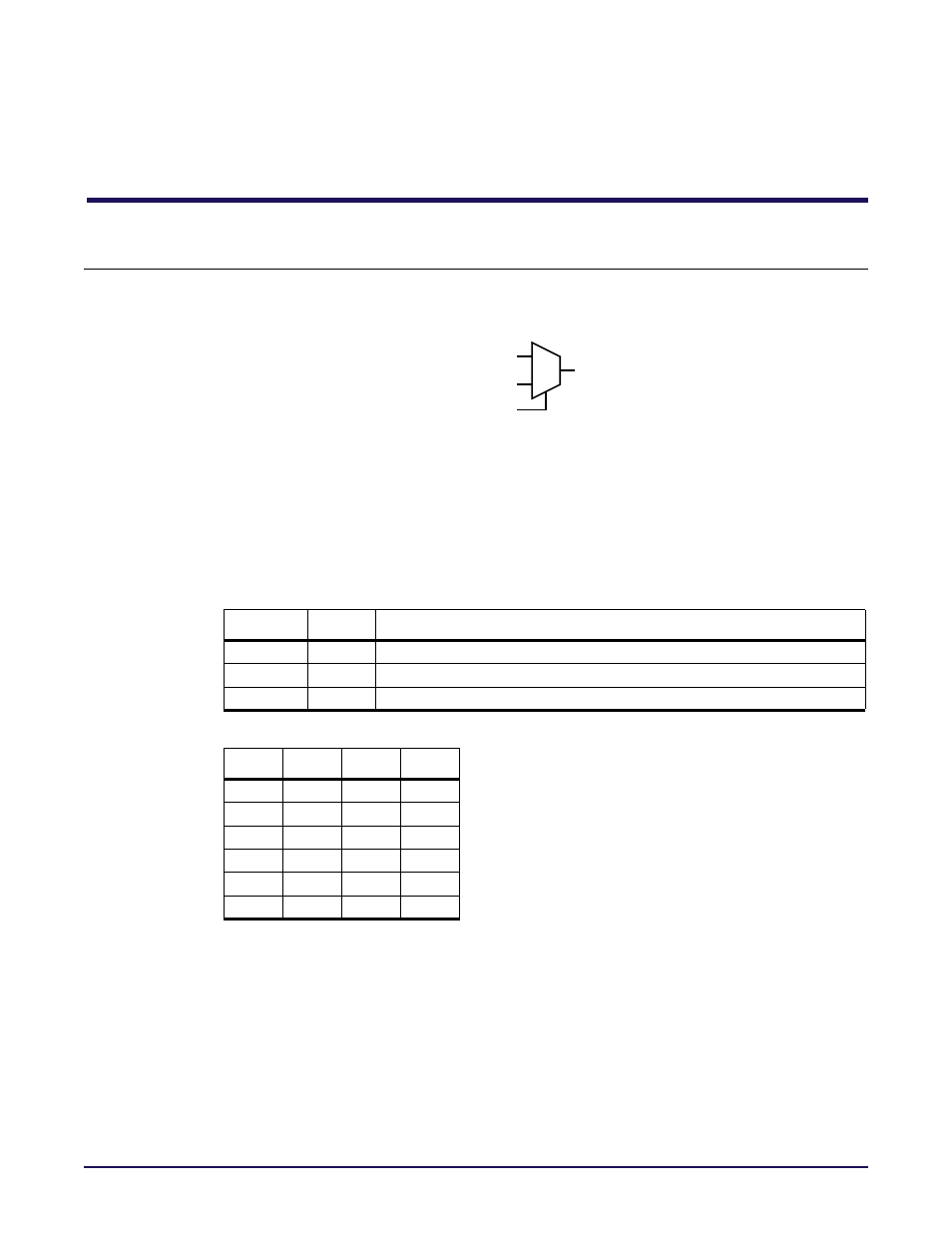
din0
MUX2
dout
din1
sel
Figure 3-1: Logic Symbol
MUX2 implements a two‐input multiplexer gate that has each of the two data inputs (din0,
din1) connected directly to the outputs of a pair of LUT4 blocks in an RLB. The MUX2, when
combined with two LUT4s, can be used as either a LUT5, a 4:1 multiplexer, or a function of up
to nine inputs.
Pins
Table 3-1: Pin Descriptions
Name
Type
Description
din0, din1
Data inputs.
sel
Data Selectinput.
dout
Data Output.
Table 3-2: Function Table
sel
din0
din1
dout
X
0
0
0
X
1
1
1
Verilog Instantiation Template
MUX2 instance_name (.dout(user_out),
.sel(user_sel),
.din0(user_din0),
.din1(user_din1));
input
input
output
0
0
X
0
0
1
X
1
1
X
0
0
1
X
1
1