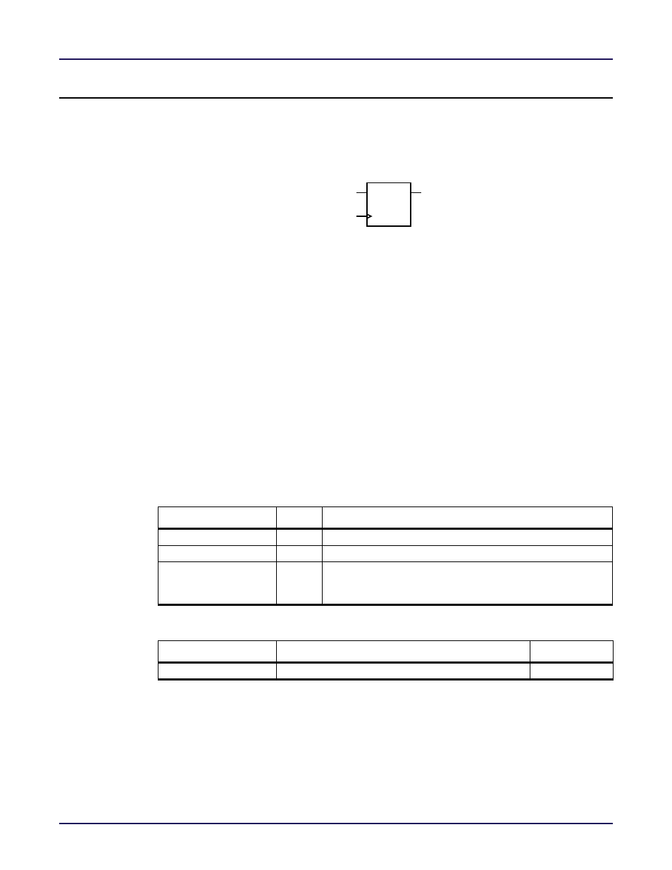
Heading1 - acx_serialize (speedster22ihp only), Heading2 - n:1 parallel-to-serial converter, Figure - figure 8-2: logic symbol – Achronix Speedster22i User Macro Guide User Manual
Page 203: Table - table 8-3: pin description, Table - table 8-4: parameters, Heading3 - verilog instantiation template, Heading3 - vhdl instantiation template, Acx_serialize (speedster22ihp only), N:1 parallel-to-serial converter
Special Functions
ACX_SERIALIZE (Speedster22iHP Only)
Speedster Macro Cell Library
PAGE 186
ACX_SERIALIZE (Speedster22iHP Only)
N:1 Parallel-to-Serial Converter
d[input_width - 1 : 0]
ck
q
ACX_DESERIALIZE
ACX_SERIALIZE implements an N:1 parallel‐to‐serial conversion of the data input, where N
is specified by the input_width parameter. The serial output stream, q, is output at N times
faster than the frequency of clk. The serialization is performed starting from the least
significant bit and proceeding to the most significant bit. ACX_SERIALIZE may be used to
rate multiply input data for higher processing rates inside the chip than is allowed at the
device pads. This block may be used in conjunction with ACX_DESERIALIZE to perform a
deserialization of data before it is driven off chip at lower rates.
Table 8-3: Pin Description
Name
Type
Description
d[input_width –1 : 0]
Data inputs.
clk
Clock.
q
Data output. The value on the q output is the LSB to MSB seri-
alization of the parallel input data d. The output data conver-
sion rate must be specified by the input_width parameter.
Table 8-4: Parameters
Parameter
Defined Values
Default Value
input_width
Note:
To make output q N‐times faster than the frequency of clk, the user needs to drive also
ACX_SERIALIZE block clock port at N‐times the frequency of clk. To create an N‐times faster clock of
the input frequency clk, user can instantiate ACX_VPLL macro.
Verilog Instantiation Template
ACX_SERIALIZE #(.input_width(4))
instance_name(.q(user_q),
.d(user_d[input_width -1 : 0]),
.clk(N-times_faster_of_user_clk));
VHDL Instantiation Template
------------- ACHRONIX LIBRARY ------------
Figure 8-2: Logic Symbol
input
input
output
positive integers
4