Heading2 - read and write count outputs, Heading3 - write count output, Heading3 - read count output – Achronix Speedster22i User Macro Guide User Manual
Page 150: Read and write count outputs, Write count output, Read count output
Memories
BRAM80KFIFO
Speedster22i Macro Cell Library
PAGE 133
Read and Write Count Outputs
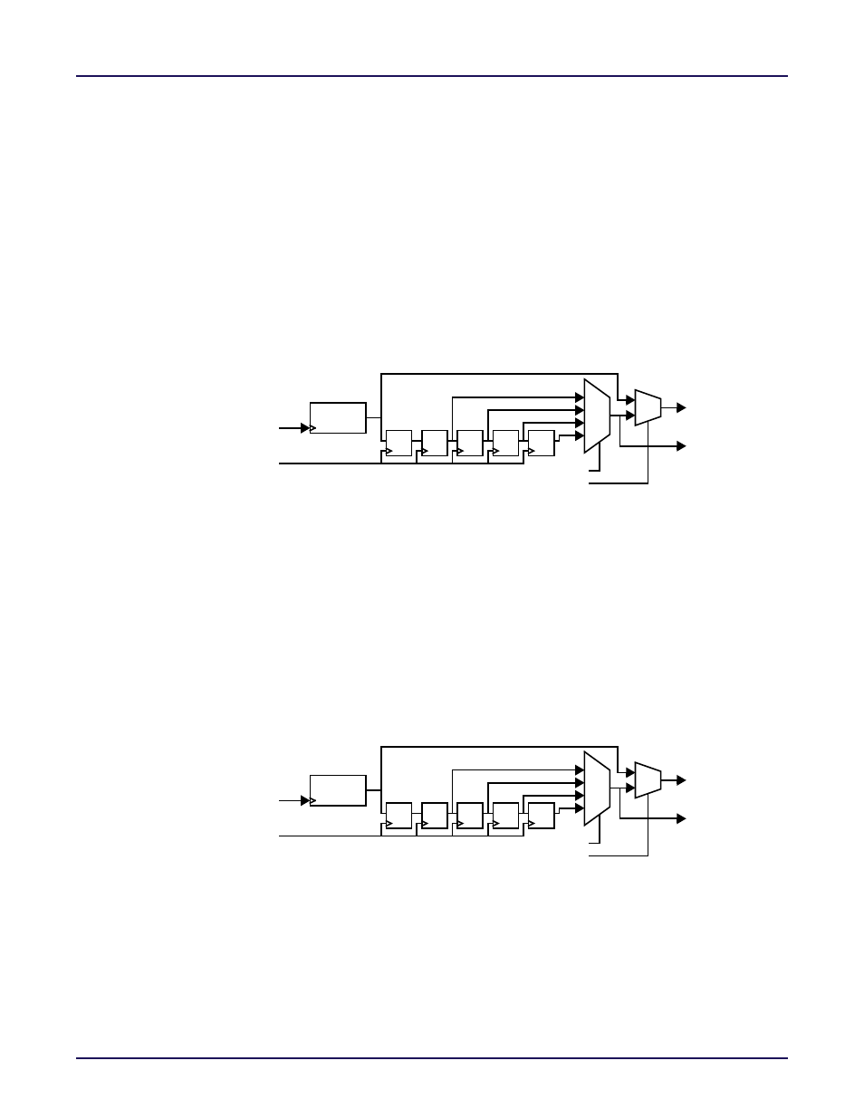
Write Count Output
The Write Count (wrcount) output of the FIFO shows the value of the Write Pointer. The
wrcount may be synchronized to either the wrclk or rdclk clock domains by setting the
wrcount_sync_mode parameter bit. Setting the wrcount_sync_mode parameter to 1’b1
outputs the wrcount directly from the Write Pointer (synchronous to the wrclk clock). Setting
the wrcount_sync_mode to 1’b0 outputs the wrcount synchronous to the rdclk output after it
has been synchronized to the rdclk clock through a synchonization circuit that is
wrptr_sync_stages + 2 registers deep. Note that if the Write Pointer is synchronized to the
rdclk clock domain, the value of the Write Counter will be delayed and have a rate of change
that will vary dependent on the rdclk clock rate.
Figure 6‐10: Write Pointer Synchronizer
shows the Write Count Output Circuit.
Figure 6-10: Write Pointer Synchronizer Block Diagram
Read Count Output
The Read Count (rdcount) output of the FIFO shows the value of the Read Pointer. The
rdcount may be synchronized to either the wrclk or rdclk clock domains by setting the
rdcount_sync_mode parameter bit. Setting the rdcount_sync_mode parameter to 1’b1
outputs the rdcount directly from the Read Pointer (synchronous to the rdclk clock). Setting
the rdcount_sync_mode parameter to 1’b0 outputs the rdcount synchronous to the wrclk
output after it has been synchronized to the wrclk clock through a synchonization circuit that
is rdptr_sync_stages + 2 registers deep. Note that if the Read Pointer is synchronized to the
wrclk clock domain, the value of the Read Counter will be delayed and have a rate of change
that will vary dependent on the wrclk clock rate.
Figure 6‐11: Read Pointer Synchronizer
shows the Read Count Output Circuit.
Figure 6-11: Read Pointer Synchronizer Block Diagram
Write
Pointer
Write Pointer Synchronizer
d q
d q
d q
d q
d q
wrcount
wrclk
rdclk
wrcount_sync_mode
wrptr_sync_stages
Synchronized
Write Pointer
used for flag
00
01
10
11
0
1
calculations
Read
Pointer
Read Pointer Synchronizer
d q
d q
d q
d q
d q
rdcount
rdclk
wrclk
rdcount_sync_mode
rdptr_sync_stages
Synchronized
Read Pointer
used for flag
00
01
10
11
0
1
calculations