Heading3 - phase frequency detector (pfd), Heading3 - feedback divider, Heading3 - clock feedback selection – Achronix Speedster22i User Macro Guide User Manual
Page 212: Table - table 9-3: clock feedback selection
PLL/DLL Clock Generators
ACX_CLKGEN
Speedster Macro Cell Library
PAGE 195
However, output cycles other than 50% are not supported at this time. If (high_cnt + low_cnt)
is an odd sum, then half_cycle must be 1 to ensure a 50% duty cycle. If enabled, when
configured with a 50% duty cycle, the Output Synthesizer will act as a simple divider.
The Output Synthesizer is optional and may be bypassed by setting the byp_clkdiv to one
Phase Frequency Detector (PFD)
The Phase Frequency Detector contains the charge pump and loop filter to control the voltage
input of the Voltage Controlled Oscillator. The VCO frequency is adjusted until the phase of
the reference clock input (after the Reference Divider) matches the phase of the clock selected
as the feedback clock into the Phase Frequency Detector. The two inputs to the PFD must be in
the range of 30 MHz to 400 MHz for the PLL to lock.
Feedback Divider
The Feedback Divider supports two modes of operation: integer mode and fractional mode.
When the Feedback Divider is set to integer mode, it has a 50% output with the division range
of 2 to 66. In fractional mode, the divider supports a division range of 8 to 66 in the integer
part. The fractional selection has a 16‐bit value which is divided by 65536.
Clock Feedback Selection
The PLL supports three modes of feedback: Internal, External, and Mixed. These modes are
selected by the intfb and phaseinc_sat parameters
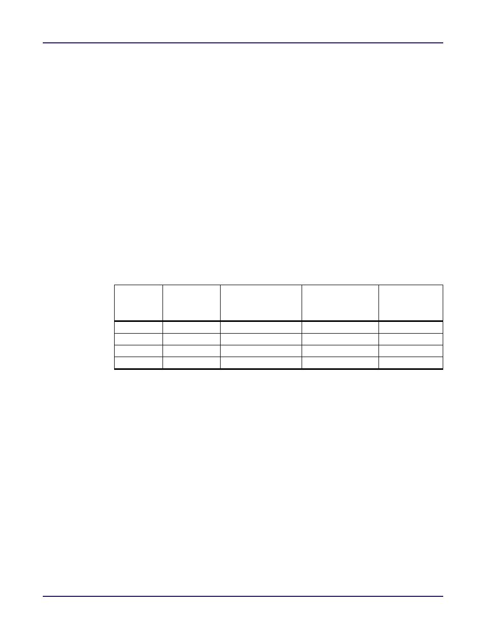
Table 9-3: Clock Feedback Selection
intfb
parameter
setting
phaseinc_sat
parameter
setting
Selected Clock
Feedback Mode
VCO Frequency
Output
Frequency
1
0
Internal Feedback
(Q/M)*Fref
Q/(M*N*P)*Fref
0
0
External Feedback
(N*P/M)*Fref
Fref/M
1
1
Mixed Mode Feedback (Q*N*P/M)*Fref
(Q/M)*Fref
0
1
Illegal combination
Internal Feedback Mode
When internal feedback mode is selected, the VCO clock is divided by the Feedback Divider
only. In this mode, the PLL can have both integer and fractional divider ratios. The PLL does
not perform deskew capability in this mode. The VCO frequency is related to the reference
clock through the relationship:
F
VCO
=(Q/M)*F
ref
in integer mode and
F
VCO
=(Q.F/M)*F
ref
in fractional mode.
External Feedback Mode
When external feedback mode is selected, the VCO clock is divided by the Output Divider
and the Output Synthesizer. In this mode only an integer divider ratio is supported (fractional
mode disabled). The clkout output of the PLL, after it has been sent through the clock
network, is fed back to the PLL for deskewing. In this mode, it is recommended to not
feedback a clock output that has been rotated by the Phase Rotator. The operation of the Phase
Rotator introduces phase errors to the PLL and can cause the PLL to unlock. The other 3 phase
rotators (the ones not in the feedback path) can be used to rotate the clock phase of the other
outputs. The VCO frequency is related to the reference clock frequency by the relationship:
F
VCO
=(N*P/M)*F
ref