Heading3 - rdrst_sync_stages, Heading3 - rdptr_sync_stages, Heading3 - wrcount_sync_mode – Achronix Speedster22i User Macro Guide User Manual
Page 147
Memories
BRAM80KFIFO
Speedster22i Macro Cell Library
PAGE 130
rdrst_sync_stages
The rdrst_sync_stages parameter defines the number of stages of registers used to
synchronize the rdrst input pin to the wrclk clock domain if the rdrst signal is used by the
Write Pointer Reset. The value of the rdrst_sync_stages parameter is only used if the
wrrst_input_mode is set to 2’b10 or 2’b11. The mapping of the rdrst_sync_stages parameter
value to the number of sychronization stages is defined in
rdrst_sync_stages Parameter Settings to Synchronization Stage Depth
, where each stage
corresponds to a register in the Read Reset Synchronizer shown in
Write Pointer Reset Input Selection Block Diagram
. For example, setting rdrst_sync_stages
to 2’b00 configures the rdrst synchronization circuit to have two back‐to‐back registers in the
Write Reset Synchronizer. The default value of the rdrst_sync_stages parameter is 2’b00.
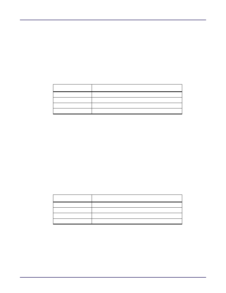
Table 6-31: Mapping rdrst_sync_stages Parameter Settings to Synchronization Stage Depth
rdrst_sync_stages
Read Reset Synchronization Stage Depth
2’b00
2
2’b01
3
2’b10
4
2’b11
5
rdptr_sync_stages
The rdptr_sync_stages parameter defines the number of stages used in the Read Pointer
Synchonizer circuit that synchronizes the Read Pointer to the wrclk clock domain. When the
FIFO is in asynchronous mode, (sync_mode = 1’b0), the output of the synchonized Read
Pointer is compared to the Write Pointer to generate the full and almost_full flags. The
synchronized Read Pointer may also be routed to the rdcounter output (rdcount_sync_mode =
1’b0). The mapping of the rdptr_sync_stages parameter value to the number of sychronization
stages is defined in
Table 6‐32: Mapping rdptr_sync_stages Parameter Settings to Synchro‐
, where each stage corresponds to a register in the Read Pointer
Synchronizer circuit shown in
Figure 6‐11: Read Pointer Synchronizer Block Diagram
Higher values for the rdptr_sync_stages parameter reduce the possibility of a metastable
event when transferring the Read Pointer across clock domains. As an example, setting
rdptr_sync_stages to 2’b00 configures the read pointer synchronization circuit to have two
back‐to‐back registers in the Read Pointer Synchonizer. The default value of the
rdptr_sync_stages parameter is 2’b00.
Table 6-32: Mapping rdptr_sync_stages Parameter Settings to Synchronization Stage Depth
rdptr_sync_stages
Read Pointer Synchronization Stage Depth
2’b00
2
2’b01
3
2’b10
4
2’b11
5
wrcount_sync_mode
The wrcount_sync_mode parameter defines whether the write counter (wrcount) output is
synchonous to the wrclk clock input. Assigning a value of 1’b0 to wrcount_sync_mode
configures the wrcount output to be synchonized to the rdclk clock. Assigning a value of 1’b1
to wrcount_sync_mode configures the wrcount output to be synchonized to the wrclk clock.
The default value of the wrcount_sync_mode parameter is 1’b1.