Heading2 - bram80k pins, Table - table 6-1: bram80k pin descriptions, Bram80k pins – Achronix Speedster22i User Macro Guide User Manual
Page 107
Memories
BRAM80K
Speedster22i Macro Cell Library
PAGE 90
BRAM80K Pins
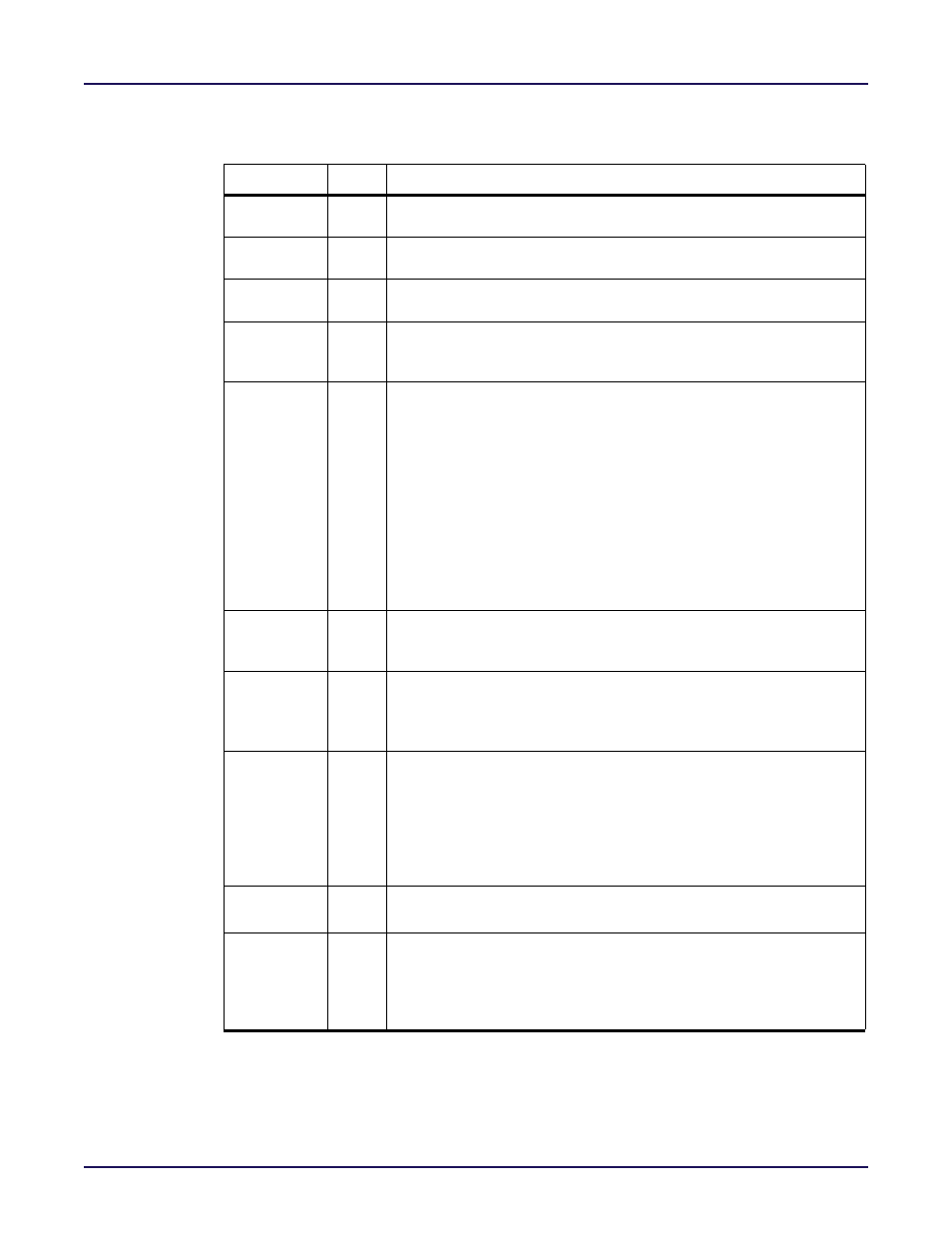
Table 6-1: BRAM80K Pin Descriptions
Name
Type
Description
dina[31:0],
dinb[31:0]
input
Port A(B) data input.
dinpa[3:0],
dinpb[3:0]
input
Port A(B) parity input (may be used for data).
dinpxa[3:0],
dinpxb[3:0]
input
Port A(B) extended parity input (may be used for data).
addra[15:0],
addrb[15:0]
input
Port A(B) read/write address input. Note that the addra, addrb
inputs are top justified. See
Table 6‐11: BRAM80K Address Bus
wea[3:0],
web[3:0]
input
Port A(B) byte-wide (10-bit) write enable. Each bit of a port’s write
enable input enables a 10-bit byte to be written to the memory block as
detailed below. Byte transactions are enabled on port A(B) when both
the corresponding write enable input wea(web) is high and the port
enable pea(peb) signal is active. For port widths of ten bits or less, all four
write enables must be tied together. For port widths of 16, 18, or 20 bits,
user_we[0] must be connected to both wea[0](web[0]) and
wea[2](web[2]) and user_we[1] must be connected to both wea[1]
(web[1]) and wea[3](web[3]). If the write enable signal is inactive while
the port enable line is active, the output is updated with the contents of
the addressed memory cells regardless of the value of the
porta_write_mode(portb_write_mode) parameter.
pea, peb
input
Port A(B) enable (programmable, default active-high = 1’b1). The
pea(peb) signal must be asserted to enable a read, write, or reset (via rst-
latcha(rstlatchb)) operation on port A(B).
rstlatcha,
rstlatchb
input
Port A(B) output latch synchronous set/reset (programmable, default
active-high = 1’b1). When rstlatcha(rstlatchab) is asserted, the value of
the porta_srval(portb_srval) parameter is written to the port a(b) output
latch upon the next active edge of clka(clkb).
rstrega,
rstregb,
input
Port A(B) output register synchronous set/reset (programmable,
default active-high = 1’b1). When rstrega(rstregb) is asserted, the value
of the porta_srval(portb_srval) parameter is written to the port a(b) out-
put register upon the next active edge of clka(clkb). The priority of
rstrega(rstregb) relative to the clock enable input outregcea(outregceb)
is determined by the value of the porta_regce_priority
(portb_regce_priority parameter).
outregcea,
outregceb
input
Port A(B) output register clock enable (active-high).
clka, clkb
input
Port A(B) clock input. Read and write operations are fully synchronous
and occur upon the active edge of the clka(clkb) clock input when the
pea(peb) signal is both high. The active edge of clka(clkb) is determined
by the value of the value of the porta_clock_polarity
(portb_clock_polarity) parameter.