Heading3 - ptr_sync_mode, Heading3 - wrptr_sync_stages, Heading3 - rdptr_sync_stages – Achronix Speedster22i User Macro Guide User Manual
Page 179: Ptr_sync_mode, Wrptr_sync_stages, Rdptr_sync_stages
Memories
LRAMFIFO
Speedster22i Macro Cell Library
PAGE 162
ptr_sync_mode
The ptr_sync_mode parameter is used to bypass the synchronization circutry between the
read and write ports when both ports are connected to the same clock. If both the wrclk and
rdclk clock inputs are connected to the same clock, the user may set the ptr_sync_mode
parameter to 1’b1 to allow faster updates to the status flags (empty, full, etc.). Note that when
ptr_sync_mode is set to 1’b1, the two clocks have to be connected to the same clock net. There
cannot be any phase difference between the two clocks in single clock mode (ptr_sync_mode =
1’b1). If the read and write clocks are connected to different clocks, the synchronization
circutry must be used and the ptr_sync_mode parameter must be set to 1’b0. The default value
of the ptr_sync_mode parameter is 1’b0.
wrptr_sync_stages
The wrptr_sync_stages parameter defines the number of stages used in the Write Pointer
Synchonizer circuit that synchronizes the Write Pointer to the rdclk clock domain. When the
FIFO is in asynchronous mode, (ptr_sync_mode = 1’b0), the output of the synchonized Write
Pointer is compared to the Read Pointer to generate the empty and almost_empty flags. The
mapping of the wrptr_sync_stages parameter value to the number of sychronization stages is
defined in
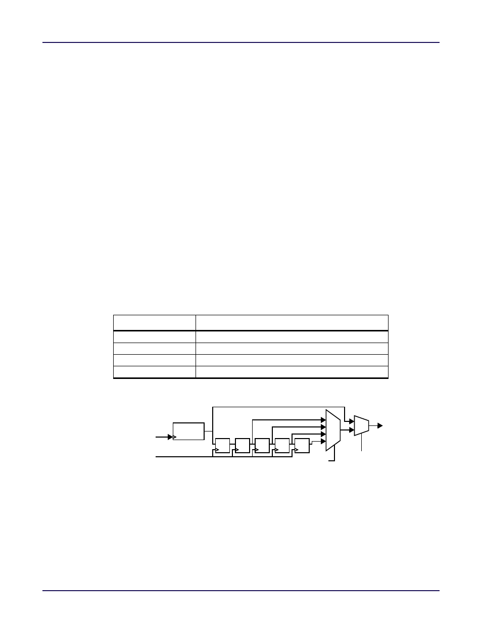
Table 6‐52: Mapping wrptr_sync_stages Parameter Settings to Synchronization
, where each stage corresponds to a register in the Write Pointer Synchronizer
circuit shown in
Figure 6‐33: Write Pointer Synchronizer Block Diagram
. Higher values for
the wrptr_sync_stages parameter reduce the possibility of a metastable event when
transferring the Write Pointer across clock domains. As an example, setting wrptr_sync_stages
to 2’b00 configures the write pointer synchronization circuit to have two back‐to‐back
registers in the Write Pointer Synchonizer. The default value of the wrptr_sync_stages
parameter is 2’b00.
Table 6-52: Mapping wrptr_sync_stages Parameter Settings to Synchronization Stage Depth
wrptr_sync_stages
Write Pointer Synchronization Stage Depth
2’b00
2
2’b01
3
2’b10
4
2’b11
5
Figure 6-33: Write Pointer Synchronizer Block Diagram
rdptr_sync_stages
The rdptr_sync_stages parameter defines the number of stages used in the Read Pointer
Synchonizer circuit that synchronizes the Read Pointer to the wrclk clock domain. When the
FIFO is in asynchronous mode, (ptr_sync_mode = 1’b0), the output of the synchonized Read
Pointer is compared to the Write Pointer to generate the full and almost_full flags. The
mapping of the rdptr_sync_stages parameter value to the number of sychronization stages is
defined in
Table 6‐53: Mapping rdptr_sync_stages Parameter Settings to Synchronization
, where each stage corresponds to a register in the Read Pointer Synchronizer
circuit shown in
Figure 6‐34: Read Pointer Synchronizer Block Diagram
. Higher values for
the rdptr_sync_stages parameter reduce the possibility of a metastable event when
Write
Pointer
Write Pointer Synchronizer
d q
d q
d q
d q
d q
wrclk
rdclk
ptr_sync_mode
wrptr_sync_stages
Synchronized
Write Pointer
used for flag
00
01
10
11
0
1
calculations