Achronix Speedster22i User Macro Guide User Manual
Page 158
Memories
BRAM80KFIFO
Speedster22i Macro Cell Library
PAGE 141
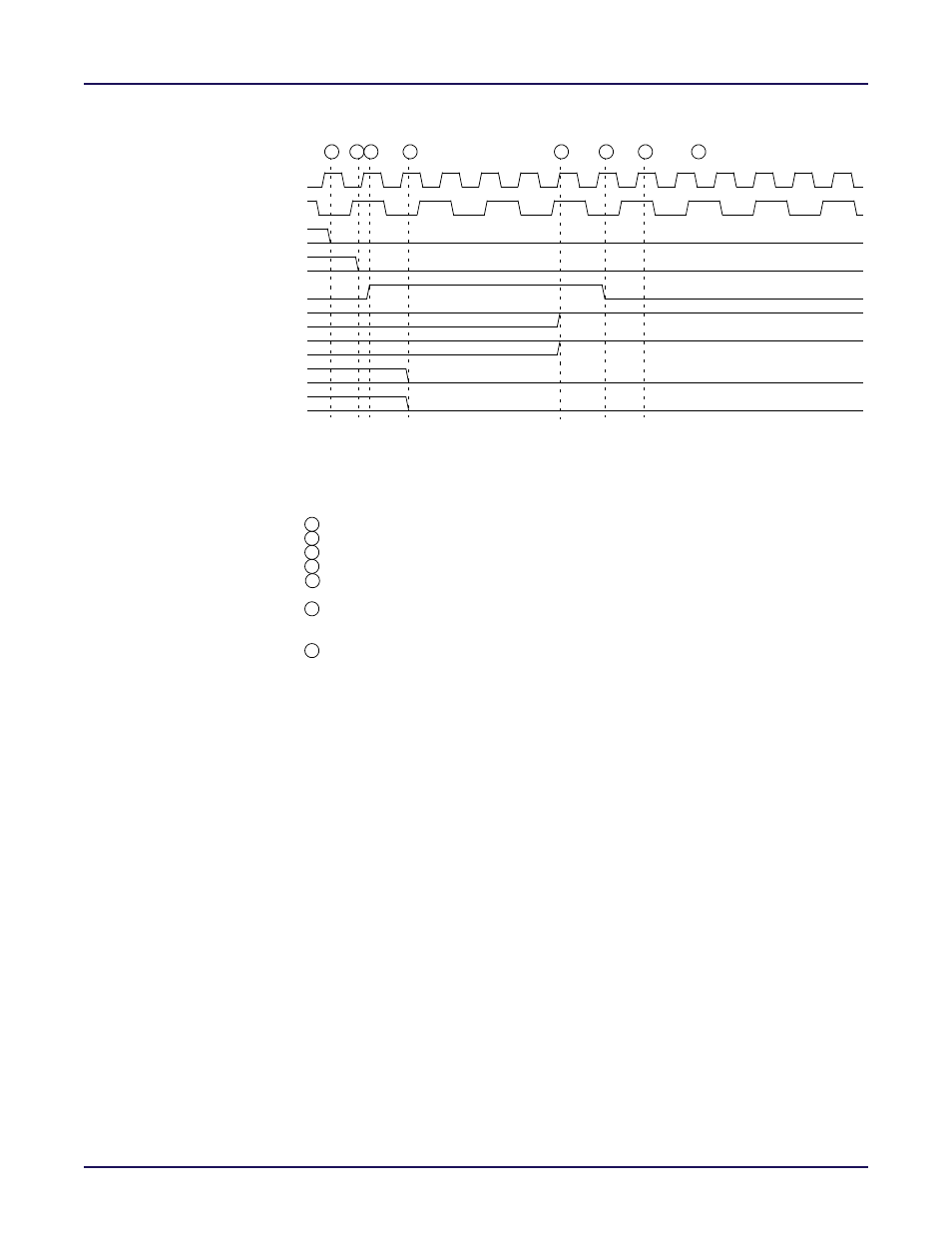
Figure 6-13: Reset Behavior Timing Diagram (Requires sync wrrst )
wrclk
rdclk
wrrst
empty
almost_empty
full
almost_full
1. wrrst input resets both the Write Pointer and the Read Pointer
Note: This timing diagram assumes:
2. Write Pointer sychronously reset by wrrst input (wrrst_input_mode = 2’b00)
3. Reset Sychronizer sychronizes wrrst input with two stages of registers
(rdrst_input_mode = 2’b11, wrrst_sync_stages = 2’b00)
4. wrrst and rdrst configured as active-high wrrst_rstval = 1’b1, rdrst_rstval = 1’b1
A
E
C
wren
rden
B C
D
F
Event : The empty and almost_empty flags are asserted (wrrst_sync_stages + 3) active rdclk edges after
Event : The user (wrrst and rdrst) reset signals are deasserted after a minimum of:
E
F
the wrrst input is asserted.
Event : The user wrrst reset signal is asserted.
C
Event : The full and almost_full flags are deasserted one active wrclk edge after wrrst is asserted.
D
max{(wrrst_sync_stages + 3) rdclk cycles, 1 wrclk cycle}
Event : The first FIFO write operation may begin one wrclk cycle
after the user wrrst reset signal is deasserted.
G
Event : The user must disable the wren signal during the reset operation.
A
after the wren and rden inputs are disabled.
Event : The user must disable the rden signal during the reset operation.
B
G