Figure - figure 9-2: acx_clkgen block diagram, Heading2 - acx_clkgen components, Heading3 - reference divider – Achronix Speedster22i User Macro Guide User Manual
Page 211: Heading3 - voltage controlled oscillator (vco), Heading3 - phase rotator with output divider, Heading3 - output synthesizer, Acx_clkgen components, Reference divider, Voltage controlled oscillator (vco), Phase rotator with output divider
PLL/DLL Clock Generators
ACX_CLKGEN
Speedster Macro Cell Library
PAGE 194
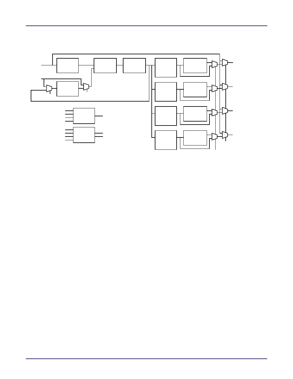
Figure 9-2: ACX_CLKGEN Block Diagram
ACX_CLKGEN Components
Reference Divider
The input reference clock can be divided by the Reference Divider. The Reference Divider
supports values from 1 to 36 and has an output with a 50% duty cycle. The frequency of the
clock after it passes through the reference divider must be in the range of 30 MHz to 400 MHz
for proper operation of the PLL.
Voltage Controlled Oscillator (VCO)
The ACX_CLKGEN must be configured so that the output of the Voltage Controlled Oscillator
falls into the range of 1000 MHz to 2000 MHz. This is accomplished by programming the
Reference, Feedback Divider, and Output Divider such that the two clock inputs to the Phase
Frequency Detector are the same and fall within the 30 MHz to 400 MHz range required by
the Phase Frequency Detector.
Phase Rotator with Output Divider
The Phase Rotator can shift the output clock phase in increments of 1/8th of the internal VCO
clock period at a time. The phase selection may be performed dynamically using the
phase_inc control input or the phase selection may be set to a static value by using the
static_phase parameter. The phase selection of each of the four outputs may be set
independently. The outphrstn input allows the four Phase Rotators to be simultaneously reset
to zero offset.
The Output Divider provides a 50% duty cycle output and supports division rates from 1 to
63. The Output divider division ratio is set independently for each of the four outputs.
Output Synthesizer
The Output Synthesizer allows the user to divide the output by (high_cnt + low_cnt), where
the ratio of high_cnt to (high_cnt + low_cnt) determines the output duty cycle.
ACX_CLKGEN
Reference
Divider (M)
Phase
Frequency
Detector
Voltage
Controlled
Oscillator
Phase
Rotator w/
Output
Feedback
Divider (Q)
Output
Synthesizer
refclk
fbclk
clkout[3]
pll_lock
rstn
outphrstn
core_clken[3:0]
phase_inc[3:0]
ick_dspll_sif_clk
ick_dspll_sif_rstn
ick_sbus_data[1:0]
ick_sbus_req
ock_sbus_ack
ock_sbus_data[1:0]
Control
Serial
Interface
Phase
Rotator w/
Output
Phase
Rotator w/
Output
Phase
Rotator w/
Output
clkout[2]
clkout[1]
clkout[0]
intfb
phaseinc_sat
bypass[3:0]
high_cnt[3:0]
low_cnt[3:0]
Divider (N)
Divider (N)
Divider (N)
Divider (N)
0
1
1
0
(P)
Output
Synthesizer
(P)
Output
Synthesizer
(P)
Output
Synthesizer
(P)