Cutout – Rockwell Automation 2711E-xxxx User Manual PanelView 1000e, 1200e 1400e User Manual
Page 56
3–6
Installing PanelView 1200e Terminals
Publication 2711E-6.17 – November 1998
Mounting a Stud-Mount Keypad or Touch Screen Terminal in a
Panel or Wall Cutout
Note: Stud-mounted terminals have a NEMA 4X rating.
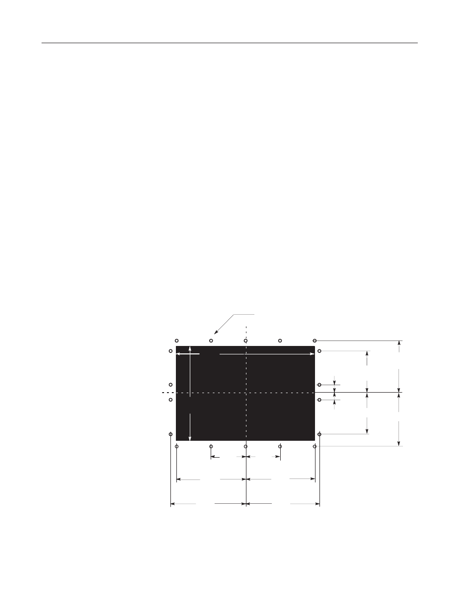
1. Make the appropriate cutout in the wall or panel location. Figures
3.4 and 3.5 show the cutout dimensions for the stud-mount
keypad and touch screen terminals. Figure 3.6 shows how the
older T30 panel cutout needs to be modified to fit the PanelView
1200e keypad terminals.
2. Place the terminal in the cutout, aligning the studs with the holes
in the rack.
3. Insert the terminal until the gasket material is flush with the wall
cutout or panel.
4. Nuts are provided with the stud-mount terminal models. Tighten
the nuts to compress the gasket on the terminal.
Built-in spacers prevent the gasket from being over-compressed. The
tightening torque increases significantly when you reach the correct
compression. At this point the tightening torque should not exceed
10 inch-pounds.
Figure 3.4 Stud-Mount Keypad Terminal Panel Cutout
CUTOUT
C
C
L
C
L
C
L
1.50
I
(38 mm)
5.50
I
(140 mm)
1.50
I
5.50
I
6.70
I
6.70
I
(170 mm)
L
4.35
I
(110 mm)
4.35
I
8.70
I
(221 mm)
8.70
I
9.16
I
(233 mm)
9.16
I
20182
12.85
I
(326 mm)
16.90”
(429 mm)
7/32
I
(5.56mm) DIA. TYP. 18 PLACES
MOUNTING STUDS ARE #10–32 SIZE
16.90
I
(429 mm)
"