Rockwell Automation 20D PowerFlex 700S AC Drives with Phase II Control Programming Manual User Manual
Page 99
Rockwell Automation Publication 20D-PM001C-EN-P - July 2013
99
Programming and Parameters
Chapter 2
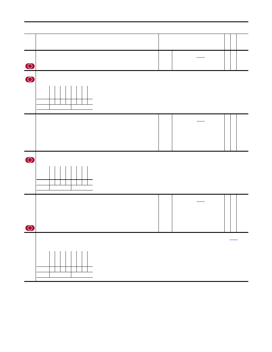
No.
Name
Description
Values
Li
nk
ab
le
Re
ad
-W
ri
te
Da
ta
T
ype
626
to
646
To DriveLogix00
to
To DriveLogix20
These parameters display the output values communicated from the PowerFlex 700S drive to the DriveLogix
controller.
Default:
Min/Max:
0
-/+32 (dependant on
[To DL DataType])
Y
RO Set by Par
625
650
DPI In DataType
Sets the data type for each word communicated from an external controller to the PowerFlex 700S drive via a DPI communication module. Setting a bit high will configure the associated word as a
Real data type and setting the bit low will configure it for Integer data type.
651
652
653
654
655
656
657
658
DPI Data In A1
DPI Data In A2
DPI Data In B1
DPI Data In B2
DPI Data In C1
DPI Data In C2
DPI Data In D1
DPI Data In D2
These parameters display the input values communicated from DPI communication modules to the PowerFlex
700S drive.
Default:
Min/Max:
0
-/+32 (dependant on
[DPI In
DataType])
RO 32-bit
Integer
659
DPI Out DataType
Sets the data type for each word communicated from the PowerFlex 700S drive to an external controller via a DPI communication module. Setting a bit high will configure the associated word as a
Real data type and setting the bit low will configure it for Integer data type.
660
661
662
663
664
665
666
667
DPI Data Out A1
DPI Data Out A2
DPI Data Out B1
DPI Data Out B2
DPI Data Out C1
DPI Data Out C2
DPI Data Out D1
DPI Data Out D2
These parameters display the output values communicated from the PowerFlex 700S drive to DPI communication
modules.
Default:
Min/Max:
0
-/+32 (dependant on
[DPI Out
DataType])
Y
RW Set by Par
659
669
Write Mask
Enables/disables write access (parameters, links, etc.) for DPI ports. Changes to this parameter only become effective when power is cycled, the drive is reset or bit 15 “Security” of
[Write
Mask Act], transitions from “1” to “0.”
Note: This parameter was added for firmware version 3.001.
Options
DP
I D2
Re
al
DP
I D1
Re
al
DP
I C2 R
eal
DP
I C1 R
eal
DP
I B
2 Re
al
DP
I B
1 Re
al
DP
I A2 R
ea
l
DP
I A1 R
ea
l
Default
0
0
0
0
0
0
0
0
Bit
7
6
5
4
3
2
1
0
0 = False
1 = True
Options
DPI
D2 R
ea
l
DPI
D1 R
ea
l
DPI
C2 Re
al
DPI
C1 Re
al
DPI
B2
Rea
l
DPI
B1
Rea
l
DPI
A2 R
eal
DPI
A1 R
eal
Default
0
0
0
0
0
0
0
0
Bit
7
6
5
4
3
2
1
0
0 = False
1 = True
Options
Dr
iv
eL
og
ix
Re
se
rv
ed
In
t D
PI C
omm
Re
se
rv
ed
Au
x DP
I C
on
n
Ex
t DPI C
onn
Lo
ca
l H
IM
Te
rm
in
al
B
lk
Default
1
1
1
x
1
1
1
1
Bit
7
6
5
4
3
2
1
0
0 = False
1 = True