Precharge board status indicators – Rockwell Automation 20D PowerFlex 700S AC Drives with Phase II Control Programming Manual User Manual
Page 143
Rockwell Automation Publication 20D-PM001C-EN-P - July 2013
143
Troubleshooting
Chapter 3
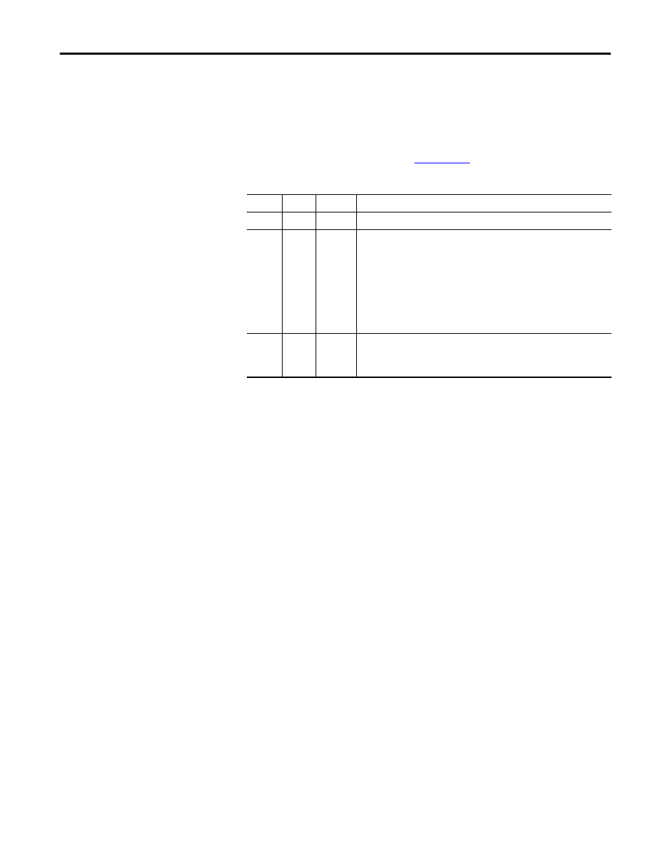
Precharge Board Status Indicators
The Precharge Board indicators (LEDs) are found on Frame 5 & 6 drives only
and are located above the “Line Type” Phase selection jumper. Refer to the
PowerFlex 700S Adjustable Frequency Drive - Phase II Control, Frames 1…6
Installation Instructions, publication
for the location of the Phase
selection jumper.
Name
Color
State
Description
Power
Green
Steady
Indicates when precharge board power supply is operational
Alarm
Yellow
Flashing
[1]
[2]
[3]
[4]
[5]
[6]
[7]
Number in “[ ]” indicates flashes and associated alarm
(1)
:
Low line voltage (<90%).
Very low line voltage (<50%).
Low phase (one phase <80% of line voltage).
Frequency out of range or asymmetry (line sync failed).
Low DC bus voltage (triggers ride-through operation).
Input frequency momentarily out of range (40-65 Hz).
DC bus short circuit detection active.
(1) An alarm condition automatically resets when the condition no longer exists
Fault
Red
Flashing
[2]
[4]
Number in “[ ]” indicates flashes and associated fault
(2)
:
DC bus short (Udc <2% after 20 ms).
Line sync failed or low line (Uac <50% Unom).
(2) A fault indicates a malfunction that must be corrected and can only be reset after cycling power.