Par 712 – Rockwell Automation 20D PowerFlex 700S AC Drives with Phase II Control Programming Manual User Manual
Page 103
Rockwell Automation Publication 20D-PM001C-EN-P - July 2013
103
Programming and Parameters
Chapter 2
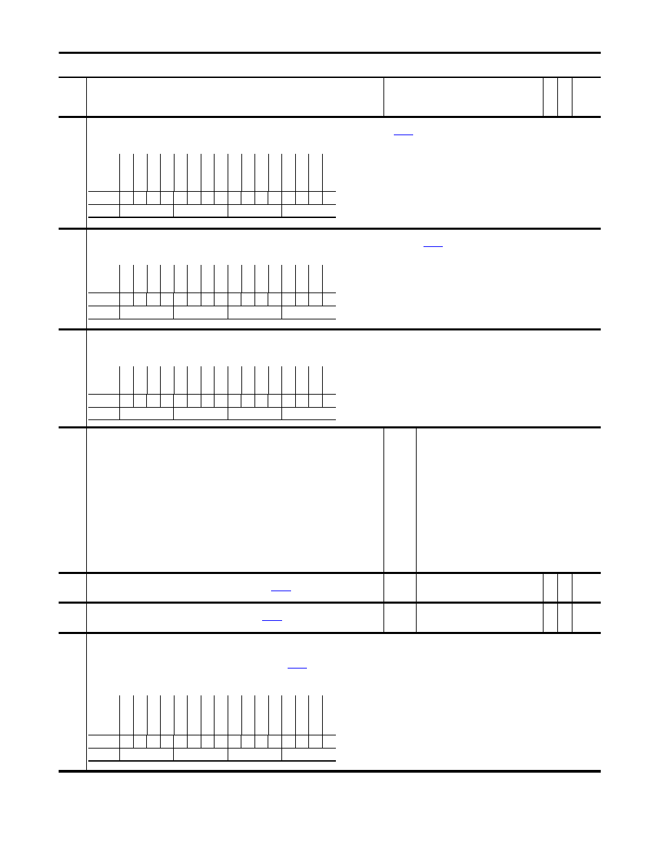
712
Write Mask Act
Status of write access for DPI ports. When bit 15 “Security” is set, network security controls the write mask instead of
[Write Mask].
Note: This parameter was added for firmware version 3.001.
713
Logic Mask Act
Indicates status of the logic mask for DPI ports. When bit 15 “Security” is set, network security controls the logic mask instead of
[Logic Mask].
Note: This parameter was added for firmware version 3.001.
714
Port Mask Act
Bits 0-5 indicate status for DPI port communication. Bit 15 “Security” indicates when security software controls the parameter.
Note: This parameter was added for firmware version 3.001.
717
PLL TP Select
Phase Locked Loop test point selection.
Note: This parameter was added for firmware version 3.001.
Default:
Options:
0 =
0 =
1 =
2 =
3 =
4 =
5 =
6 =
7 =
8 =
9 =
10 =
11 =
12 =
13 =
14 =
“Zero”
“Zero”
15 = “Vel Lpf In”
“Bg Once”
16 = “Vel Lpf Out”
“Position Err”
17 = “k1”
“X to V”
18 = “k2”
“Dt”
19 = ”k3”
“Gain”
20 = “pi”
“Pos Intg”
21 = “Ve Enable”
“Cal”
22 = “Ve In”
“Epr Cal”
23 = “Ve Out”
“Num”
24 = “Ve AnaPlsScl”
“Denom”
25 = “Ve Whl Accum”
“Egr Ratio”
26 = “Ve Frc AccmF”
“A Comp”
27 = “Ve Frc AccmI”
“H Comp”
28 = “Ve Dt”
“Pos Lpf Out”
718
PLL TP DataDInt
Test point integer data. This data is meaningful only if the selection at
[PLL TP Select] is integer data.
Note: This parameter was added for firmware version 3.001.
Default:
Min/Max:
0
-/+2147483648
RO 32-bit
Integer
719
PLL TP DataReal
Test point real data. This data is meaningful only if the selection at
[PLL TP Select] is not integer data.
Note: This parameter was added for firmware version 3.001.
Default:
Min/Max:
0.0
-/+2200000000.0000
RO Real
720
PLL Control
Phase Locked Loop Control.
Bit 0 “Vel FdFwd En” - When set, enables the velocity feed forward path. When cleared, the feed forward path is disabled.
Bit 1 “Ext Vel In” - When set, enables external velocity feed forward through
[PLL Ext Spd Ref]. When cleared, velocity feed forward is derived from the input device position.
Bit 2 “Trckng AComp” - When set, provides an element of acceleration compensation to the feed forward branch. This is not recommended for use with external inputs because of increased noise.
Note: This parameter was added for firmware version 3.001.
No.
Name
Description
Values
Link
able
Re
ad
-Write
Da
ta
T
yp
e
Options
Sec
ur
ity
Re
se
rv
ed
Re
se
rv
ed
Re
se
rv
ed
Re
se
rv
ed
Re
se
rv
ed
Re
se
rv
ed
Re
se
rv
ed
Dr
iv
eL
og
ix
Re
se
rv
ed
In
t D
PI C
omm
Re
se
rv
ed
Au
x DP
I C
on
n
Ex
t DPI
Conn
Lo
ca
l H
IM
Te
rm
in
al
B
lk
Default
0
x
x
x
x
x
x
x
0
x
0
x
0
0
0
0
Bit
15 14 13 12 11 10 9
8
7
6
5
4
3
2
1
0
0 = False
1 = True
Options
Se
cu
rit
y
Re
ser
ve
d
Re
ser
ve
d
Re
ser
ve
d
Re
ser
ve
d
Re
ser
ve
d
Re
ser
ve
d
Re
ser
ve
d
Re
ser
ve
d
Re
ser
ve
d
DPI
P
or
t 5
Re
ser
ve
d
DPI
P
or
t 3
DPI
P
or
t 2
DPI
P
or
t 1
Di
gi
ta
l I
n
Default
0
x
x
x
x
x
x
x
x
x
0
x
0
0
0
0
Bit
15 14 13 12 11 10 9
8
7
6
5
4
3
2
1
0
0 = False
1 = True
Options
Sec
ur
ity
Re
se
rv
ed
Re
se
rv
ed
Re
se
rv
ed
Re
se
rv
ed
Re
se
rv
ed
Re
se
rv
ed
Re
se
rv
ed
Re
se
rv
ed
Re
se
rv
ed
DP
I P
or
t 5
Re
se
rv
ed
DP
I P
or
t 3
DP
I P
or
t 2
DP
I P
or
t 1
Dig
ital
In
Default
0
x
x
x
x
x
x
x
x
x
0
x
0
0
0
0
Bit
15 14 13 12 11 10 9
8
7
6
5
4
3
2
1
0
0 = False
1 = True
Options
Re
se
rv
ed
Re
se
rv
ed
Re
se
rv
ed
Re
se
rv
ed
Re
se
rv
ed
Re
se
rv
ed
Re
se
rv
ed
Re
se
rv
ed
Re
se
rv
ed
Re
se
rv
ed
Re
se
rv
ed
Re
se
rv
ed
Tr
ck
ng
H
Co
m
p
Tr
ck
ng
A
Co
m
p
Ex
t V
el
In
Ve
l F
dF
w
d E
n
Default
x
x
x
x
x
x
x
x
x
x
x
x
0
0
0
0
Bit
15 14 13 12 11 10 9
8
7
6
5
4
3
2
1
0
0 = False
1 = True