O], and – Rockwell Automation 20D PowerFlex 700S AC Drives with Phase II Control Programming Manual User Manual
Page 114
114
Rockwell Automation Publication 20D-PM001C-EN-P - July 2013
Chapter 2
Programming and Parameters
831
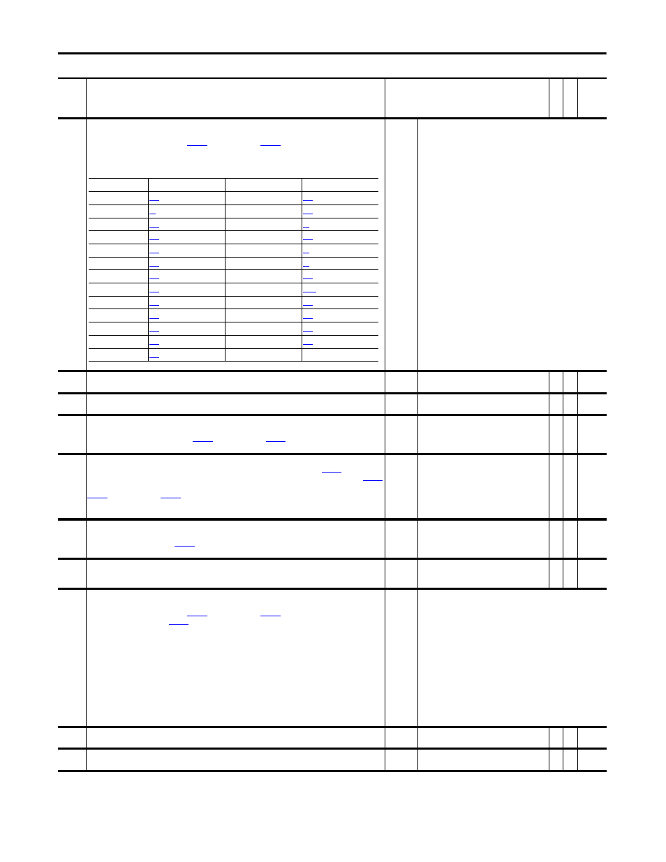
Anlg Out1 Sel
Identifies the signal used on Analog Output 1. If the desired signal is not available in the selection list, choose
option 0 - “User Select” and link with
[Anlg Out1 DInt] or
[Anlg Out1 Real] to select the desired
parameter for output.
The following table provides the parameter that corresponds to the option selected in this parameter.
Default:
Options:
17 =
0 =
1 =
2 =
3 =
4 =
5 =
6 =
7 =
8 =
9 =
10 =
11 =
12 =
13 =
“Speed Fdbk”
“User Select”
14 = “Reserved”
“Output Freq”
15 = “Motor TrqRef”
“Sel Spd Ref”
16 = “MtrTrqCurRef”
“Output Curr”
17 = “Speed Ref”
“Trq Cur (Iq)”
18 = “Speed Fdbk”
“% Motor Flux”
19 = “Torque Est”
“Output Power”
20 = “Scl Spd Fdbk”
“Output Volts”
21 = “RampedSpdRef”
“DC Bus Volts”
22 = “Spd Reg Out”
“PI Reference”
23 = “MOP Level”
“PI Feedback”
24 = “Trend 1 DInt”
“PI Error”
25 = “Trend 1 Real”
“PI Output”
26 = “Trend 2 DInt”
“Reserved”
27 = “Trend 2 Real”
832
Anlg Out1 DInt
Link this parameter to an integer source parameter that will control Analog Output 1.
Default:
Min/Max:
0
-/+2147483648
Y
RW 32-bit
Integer
833
Anlg Out1 Real
Link this parameter to a real (floating point) source parameter that will control Analog Output 1.
Default:
Min/Max:
0.0000
-/+2200000000.0000.0000
Y
RW Real
834
Anlg Out1 Offset
Provides an offset for Analog Output 1 before the scaling and limit blocks in the Analog Output 1 function. This
parameter value is summed with either
[Anlg Out1 DInt] or
[Anlg Out1 Real] at the beginning of
the function.
Default:
Min/Max:
0.0000
-/+2200000000.0000
Y
RW Real
835
Anlg Out1 Scale
Scales the range of the source parameter to the range of Analog Output 1. For example: If
[Anlg Out1 Sel]
is set to 1 “Output Freq”, the output frequency of the drive is 0 - 60Hz and you enter “6” in this parameter,
[Anlg Out1 Value] = 6Hz per 1V, or 0 - 60Hz.
[Anlg Out1 DInt] or
[Anlg Out1 Real] is multiplied by this number after the limit function.
Note: The turn-off point for this parameter has been changed from ±0.001 to ±0.0001 for firmware version
4.002.
Default:
Min/Max:
Units:
0.0000
-/+2200000000.0000
/V
Y
RW Real
836
Anlg Out1 Zero
Applies an offset to the scaled value of Analog Output 1. This parameter is summed with the output of the
scaling block. This sum produces
[Anlg Out1 Value]. Typically this value corresponds to 0V for Analog
Output 1.
Default:
Min/Max:
Units:
0.0000
-/+20.0000
V
Y
RW Real
837
Anlg Out1 Value
Displays the voltage reference for Analog Output 1 before the digital to analog conversion.
Default:
Min/Max:
Units:
0.0000
-/+10.0000
V
RO Real
838
Anlg Out2 Sel
Identifies the signal used on Analog Output 2. If the desired signal is not available in the selection list, choose
option 0 - “User Select” and link with
[Anlg Out2 DInt] or
[Anlg Out2 Real] to select the desired
parameter for output. Refer to
for a list of parameters that correspond to the option selected in this
parameter.
Default:
Options:
3 =
0 =
1 =
2 =
3 =
4 =
5 =
6 =
7 =
8 =
9 =
10 =
11 =
12 =
13 =
“Output Curr”
“User Select”
14 = “Reserved”
“Output Freq”
15 = “Motor TrqRef”
“Sel Spd Ref”
16 = “MtrTrqCurRef”
“Output Curr”
17 = “Speed Ref”
“Trq Cur (Iq)”
18 = “Speed Fdbk”
“% Motor Flux”
19 = “Torque Est”
“Output Power”
20 = “Scl Spd Fdbk”
“Output Volts”
21 = “RampedSpdRef”
“DC Bus Volts”
22 = “Spd Reg Out”
“PI Reference”
23 = “MOP Level”
“PI Feedback”
24 = “Trend 1 DInt”
“PI Error”
25 = “Trend 1 Real”
“PI Output”
26 = “Trend 2 DInt”
“Reserved”
27 = “Trend 2 Real”
839
Anlg Out2 DInt
Link this parameter to an integer source parameter that will control Analog Output 2.
Default:
Min/Max:
0
-/+2147483648
Y
RW 32-bit
Integer
840
Anlg Out2 Real
Link this parameter to a real (floating point) source parameter that will control Analog Output 2.
Default:
Min/Max:
0.0000
-/+2200000000.0000
Y
RW Real
No.
Name
Description
Values
Link
able
Re
ad
-Write
Da
ta
T
yp
e
Option
Parameter
Option
Parameter
1 “Output Freq”
[Output Freq]
16 “MtrTrqCurRef”
[Mtr Trq Curr Ref]
2 “Sel Spd Ref”
[Selected Spd Ref]
17 “Speed Ref”
[Motor Speed Ref]
3 “Output Curr”
[Output Current]
18 “Speed Fdbk”
[Filtered SpdFdbk]
4 “Trq Cur (Iq)”
[Trq Cur Fdbk (Iq)]
19 “Torque Est”
[Estimated Torque]
5 “% Motor Flux”
[% Motor Flux]
20 “Scl Spd Fdbk”
[Scaled Spd Fdbk]
6 “Output Power”
[Output Power]
21 “RampedSpdRef”
[Ramped Spd Ref]
7 “Output Volts”
[Output Voltage]
22 “Spd Reg Out”
[SpdReg Integ Out]
8 “DC Bus Volts”
[DC Bus Voltage]
23 “MOP Level”
[MOP Level Real]
9 “PI Reference”
[PI Reference]
24 “Trend 1 DInt”
[Trend Out1 DInt]
10 “PI Feedback”
[PI Feedback]
25 “Trend 1 Real”
[Trend Out1 Real]
11 “PI Error”
[PI Error]
26 “Trend 2 DInt”
[Trend Out2 DInt]
12 “PI Output”
[PI Output]
27 “Trend 2 Real”
[Trend Out2 Real]
15 “Motor TrqRef”
[Motor Torque Ref]