Par 236 – Rockwell Automation 20D PowerFlex 700S AC Drives with Phase II Control Programming Manual User Manual
Page 52
52
Rockwell Automation Publication 20D-PM001C-EN-P - July 2013
Chapter 2
Programming and Parameters
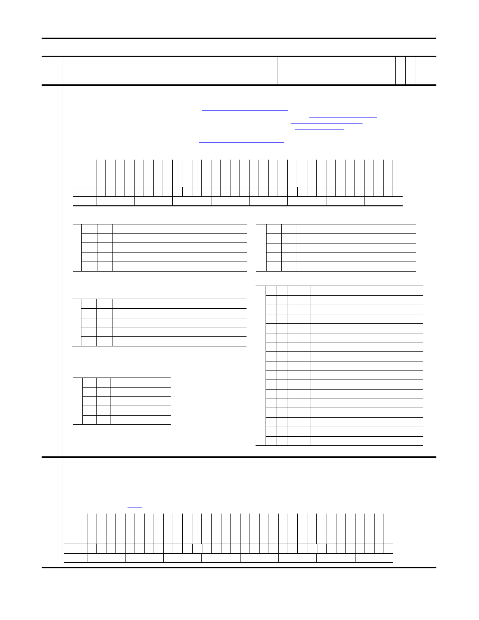
236 RegisLtch
0/1Cnfg
Configures the registration latch at port 0 or port 1 to be used with Encoder 0 or Encoder 1, respectively.
• Bit 0 “RL0 Encoder 1” selects the encoder for the input source of latched data. Setting bit 0 selects encoder 1, resetting the bit to zero selects encoder 0.
• Bits 1 “RL0 TrgSrc0” and 2 “RL0 TrgSrc1” select the trigger source (see
Table 236A: Encoder0 Trigger Source Settings
).
• Bits 3 “RL0 TrgEdge0”, 4 “RL0 TrgEdge1”, 19 “RL1 TrgEdge0” and 20 “RL1 TrgEdge1” select which edges signal the position (see
Table 236C: Edge Selection Settings
).
• Bits 5 “RL0 Dir Rev”, 6 “RL0 Dir Fwd”, 21 “RL1 Dir Rev” and 22 “RL1 Dir Fwd” set the direction of position capture (see
Table 236D: Trigger Direction Settings
).
• Bits 8 “SL DI Filt 0”, 9 “SL DI Filt 1”, 10 “SL DI Filt 2”, and 11 “SL DI Filt 3” configure a filter for the digital input 1 and 2 (see
). The filter requires the input signal to be stable
for the specified time period. Input transitions within the filter time setting will be ignored. Bits 8-11 add 100ns filter per stage to external trigger.
• 17 “RL1 TrgSrc0” and 18 “RL1 TrgSrc1” select the trigger source (see
Table 236B: Encoder1 Trigger Source Settings
).
• Bit 0 &16 - off = Enc0 input to latch, on = Enc1 input to latch.
237 RegisLtch0/1
Ctrl
Configures the control for registration latch 0 and 1.
• Set bit 0 “RL0 Arm Req” and bit 16 “RL1 Arm Req” to arm the registration logic for the next trigger event. The particular latch will be armed and ready to be strobed on the next occurrence of the
trigger input.
• Set bit 1 “RL0 DisarmReq” and bit 17 “RL1 DisarmReq” to disarm the registration logic for next trigger event.
After the registration is captured, bit 0 “RL0 Arm Req” and bit 16 “RL1 Arm Req” automatically resets back to 0 after found. Bit 1 “RL0 DisarmReq” and bit 17 “RL1 DisarmReq” are only needed to
disarm a registration latch that has not been found yet. Setting bits 1 and 17 will clear the bits 0 and 6. Setting bits 0 and 6 sets bits 0 “RL0 Armed” and bit 16 “RL1 Armed” and clears bits 1 “RL0
Found” and bit 17 “RL1 Found” of
[RegisLtch0/1Stat].
No.
Name
Description
Values
Link
able
Re
ad
-Write
Da
ta
T
yp
e
Table 236A: Encoder0 Trigger Source Settings
Note: When the Z-pulse is selected as a trigger source, registration latch port 0 is used for
Encoder0 regardless of the setting of bit 0 “RL0 Encoder1”.
Bit
2
1
0
0
Encoder 0 Z-pulse AND Ext Trig A
0
1
Ext Trig B (Digital Input 2)
1
0
Ext Trig A (Digital Input 1)
1
1
Encoder 0 (Primary Encoder) Z-pulse
Table 236D: Trigger Direction Settings
Bit
6/22 5/21
0
0
Not Configured
0
1
Reverse
1
0
Forward
1
1
Both Directions
Table 236E: Filter Settings
Bit
11
10
9
8 Input Filter Setting
0
0
0
0 Filter disabled
0
0
0
1 100 ns filter
0
0
1
0 200 ns filter
0
0
1
1 300 ns filter
0
1
0
0 400 ns filter
0
1
0
1 500 ns filter
0
1
1
0 600 ns filter
0
1
1
1 700 ns filter
1
0
0
0 800 ns filter (default setting)
1
0
0
1 900 ns filter
1
0
1
0 1000 ns filter
1
0
1
1 1100 ns filter
1
1
0
0 1200 ns filter
1
1
0
1 1300 ns filter
1
1
1
0 1400 ns filter
1
1
1
1 1500 ns filter
Options
Re
se
rv
ed
Re
se
rv
ed
Re
se
rv
ed
Re
se
rv
ed
Re
se
rv
ed
Re
se
rv
ed
Re
se
rv
ed
Re
se
rv
ed
Re
se
rv
ed
RL1
Dir F
w
d
RL1
Dir R
ev
RL1 T
rgE
dge1
RL1 T
rgE
dge0
RL1
T
rgSr
c1
RL1
T
rgSr
c0
RL1
E
nc
oder1
Re
se
rv
ed
Re
se
rv
ed
Re
se
rv
ed
Re
se
rv
ed
SL
D
I F
ilt
3
SL
D
I F
ilt
2
SL
D
I F
ilt
1
SL
D
I F
ilt
0
Re
se
rv
ed
RL0
Dir F
w
d
RL0
Dir R
ev
RL0 T
rgE
dge1
RL0 T
rgE
dge0
RL0
T
rgSr
c1
RL0
T
rgSr
c0
RL0
E
nc
oder1
Default
x
x
x
x
x
x
x
x
x
0
0
0
0
0
0
0
x
x
x
x
0
0
0
0
x
1
1
0
0
0
1
1
Bit
31 30 29 28 27 26 25 24 23 22 21 20 19 18 17 16 15 14 13 12 11 10 9
8
7
6
5
4
3
2
1
0
Table 236C: Edge Selection Settings
Bit 4/20 3/19
0
0
Capture on rising edge
0
1
Capture on falling edge
1
0
Capture on both edges
1
1
Disable capture
0 = False
1 = True
Table 236B: Encoder1 Trigger Source Settings
Note: When the Z-pulse is selected as a trigger source, registration latch port 1 is used for
Encoder1 regardless of the setting of bit 16 “RL1 Encoder1”.
Bit
18
17
0
0
Encoder 1 Z-pulse AND Ext Trig A
0
1
Ext Trig B (Digital Input 2)
1
0
Ext Trig A (Digital Input 1)
1
1
Encoder 1 (Secondary Encoder) Z-pulse
Options
Re
ser
ve
d
Re
ser
ve
d
Re
ser
ve
d
Re
ser
ve
d
Re
ser
ve
d
Re
ser
ve
d
Re
ser
ve
d
Re
ser
ve
d
Re
ser
ve
d
Re
ser
ve
d
Re
ser
ve
d
Re
ser
ve
d
Re
ser
ve
d
Re
ser
ve
d
RL1 D
isa
rm
Req
RL1 Arm
R
eq
Re
ser
ve
d
Re
ser
ve
d
Re
ser
ve
d
Re
ser
ve
d
Re
ser
ve
d
Re
ser
ve
d
Re
ser
ve
d
Re
ser
ve
d
Re
ser
ve
d
Re
ser
ve
d
Re
ser
ve
d
Re
ser
ve
d
Re
ser
ve
d
Re
ser
ve
d
RL0 D
isa
rm
Req
RL0 Arm
R
eq
Default
x
x
x
x
x
x
x
x
x
x
x
x
x
x
0
0
x
x
x
x
x
x
x
x
x
x
x
x
x
x
0
0
Bit
31 30 29 28 27 26 25 24 23 22 21 20 19 18 17 16 15 14 13 12 11 10 9
8
7
6
5
4
3
2
1
0
0 = False
1 = True