Rockwell Automation 20D PowerFlex 700S AC Drives with Phase II Control Programming Manual User Manual
Page 41
Rockwell Automation Publication 20D-PM001C-EN-P - July 2013
41
Programming and Parameters
Chapter 2
132
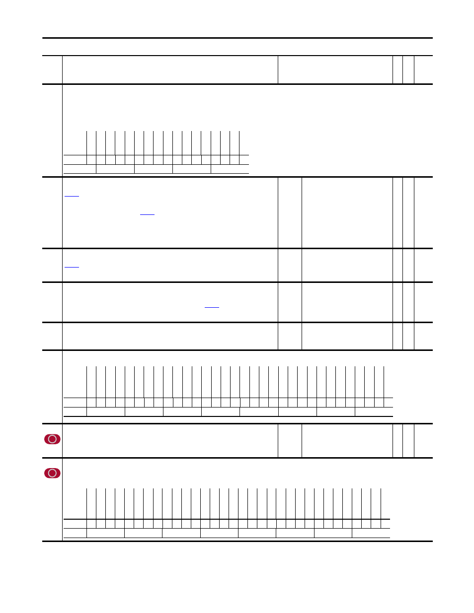
Inert Adapt Sel
Configures the Inertia Adaptation Algorithm (IAA Function).
• Bit 0 “Inrtia Adapt” when set to 1 (on), the Inertia Adaptation function will effect enhanced stability, higher bandwidths and dynamic stiffness. Useful when systems with a gear-box becomes
disconnected from the load. Also used with motors that have very little inertia that otherwise lack dynamic stiffness, even at high bandwidths.
• Bit 1 “Load Est” when set to 1 (on), the Load Estimate option removes or greatly reduces load disturbances and gives quicker system response.
• Bit 2 “First Diff” selects the first difference feedback for Inertia Adaptation.
Notes: When setting both Bit 0 & 1, stability is enhanced and load disturbances are removed. Bit 2 “First Diff” was added for firmware version 3.001.
133
Inert Adapt BW
This parameter sets the bandwidth of the Inertia Adaptation function when the IAA function is selected
(
[Inert Adapt Sel], bit 0 = 1). Typical IAA bandwidths range from 70 to 150 rad/sec with 100 rad/sec
nominal best.
If the Load Estimate function is selected (
[Inert Adapt Sel], bit 0 = 1), then this parameter sets the natural
frequency of a filter in rad/sec. Typical values range from 10 to 150 rad/sec with higher values being more
responsive to disturbances but with increased system noise. There is no nominal best value, but 40 rad/sec is a
suggested starting point. This adjustment may not function well in 'sloppy' geared systems.
If both Inertia Adaptation and Load Estimate functions are active, use a bandwidth setting of 100 rad/sec.
Default:
Min/Max:
Units:
100.0000
10.0000/250.0000
rad/s
Y
RW Real
134
Inert Adapt Gain
This parameter sets a multiplier of system inertia when the Inertia Adaptation function is selected
(
[Inert Adapt Sel], bit 0 = 1). Higher values may cause high frequency ringing, while smaller values may
cause fundamental load instability. A typical value is 0.5 This parameter has no affect on the Load Estimate
function.
Default:
Min/Max:
0.500
0.300/1.000
Y
RW Real
136
137
138
Skip Speed 1
Skip Speed 2
Skip Speed 3
Sets a frequency at which the drive will not operate. [Skip Speed 1 - 3] and
equal 0.
Note: These parameters were added for firmware version 2.003.
Default:
Min/Max:
Units:
0.0
–/+30000.0
rpm
Y
RW 16-bit
Integer
139
Skip Speed Band
Determines the bandwidth around a skip frequency. [Skip Speed Band] is split, applying 1/2 above and 1/2 below
the actual skip frequency. The same bandwidth applies to all skip frequencies.
Note: This parameter was added for firmware version 2.003.
Default:
Min/Max:
Units:
0.0
0.0/1000.0
rpm
Y
RW 16-bit
Integer
145
Hardware Present
Indicates if optional hardware is installed.
146
FW TaskTime Sel
Sets the scan times for the drive firmware. Changing the firmware scan times will affect drive performance. Faster
scan times may allow for higher bandwidth of the internal regulators. To achieve faster scan times some functions
may need to be disabled. Only the most demanding application may benefit from faster scan times. Typically,
adjusting this parameter is not needed, it is recommended you consult the factory before changing.
Default:
Options:
0 =
0 =
1 =
2 =
“0.5 /2 /8ms”
“0.5 /2 /8ms”
“0.5 /1 /8ms”
“0.25 /1 /8ms”
RW 16-bit
Integer
147
FW Functions En
Allows specific firmware functions to be disabled. When a bit is false, the associated function is disabled and all related parameters will be hidden. When a bit is true, the associated function is
enabled and all related parameters will be displayed.
Notes: Bits 18, 20, & 21 were changed to “Reserved” for firmware version 2.004. Bit 19 “MotinPlanner” and 24 “PhaseLockLp” were added for firmware version 3.001.
No.
Name
Description
Values
Link
able
Re
ad
-Write
Da
ta
T
yp
e
Options
Re
se
rv
ed
Re
se
rv
ed
Re
se
rv
ed
Re
se
rv
ed
Re
se
rv
ed
Re
se
rv
ed
Re
se
rv
ed
Re
se
rv
ed
Re
se
rv
ed
Re
se
rv
ed
Re
se
rv
ed
Re
se
rv
ed
Re
se
rv
ed
Re
se
rv
ed
Fir
st
D
iff
Lo
ad
E
st
Inr
tia
A
da
pt
Default
x
x
x
x
x
x
x
x
x
x
x
x
x
x
0
0
0
Bit
16 15 14 13 12 11 10 9
8
7
6
5
4
3
2
1
0
0 = False
1 = True
Options
Re
se
rv
ed
Re
se
rv
ed
Re
se
rv
ed
Re
se
rv
ed
Re
se
rv
ed
Re
se
rv
ed
Re
se
rv
ed
Re
se
rv
ed
Re
se
rv
ed
Re
se
rv
ed
Re
se
rv
ed
Re
se
rv
ed
Re
se
rv
ed
Re
se
rv
ed
Re
se
rv
ed
Driv
eL
ogix
St
ahl F
dbck
Re
se
rv
ed
Te
mposonF
dbk
Re
sol
ve
r Brd
MDI
Br
d
H
eidenhain
St
egmannHiRs
2nd Enc
ode
r
Re
se
rv
ed
Re
se
rv
ed
Sa
feO
ff B
rd
Re
se
rv
ed
Sy
nchLinkBr
d
Re
se
rv
ed
Em
be
dded
ENET
DPI
C
om
m
B
rd
Default
x
x
x
x
x
x
x
x
x
x
x
x
x
x
x
0
0
x
0
0
0
0
0
0
x
x
0
x
0
x
0
0
Bit
31 30 29 28 27 26 25 24 23 22 21 20 19 18 17 16 15 14 13 12 11 10 9
8
7
6
5
4
3
2
1
0
0 = False
1 = True
Options
Dv
lp
m
nt
De
Bu
g
Tr
en
di
ng
Re
se
rv
ed
Pe
ak
D
et
ec
t
Te
st
P
oi
nt
s
Re
se
rv
ed
Re
se
rv
ed
Ph
ase
L
oc
kL
p
Sy
nc G
ener
Po
sW
tc
h/
D
tc
t
Re
se
rv
ed
Re
se
rv
ed
MotinPlanner
Re
se
rv
ed
Re
se
rv
ed
Po
si
tio
nC
tr
l
DI
Bi
tS
w
ap
s
D
igital Outs
Analog Ou
ts
Analog In
s
PF
700S
Re
se
rv
ed
Re
se
rv
ed
Lim
/F
unc Gen
Pr
oc
es
s T
rim
Re
se
rv
ed
Sp
ee
d R
eg
Vi
rt
E
nc
od
er
Fric
tionC
omp
Ine
rtia
C
om
p
Spd Ref Ctr
l
Spd Ref S
el
Default
1
1
x
1
1
x
x
0
1
1
x
x
0
x
x
0
1
1
1
1
1
x
x
1
1
x
1
1
1
1
1
1
Bit
31 30 29 28 27 26 25 24 23 22 21 20 19 18 17 16 15 14 13 12 11 10 9
8
7
6
5
4
3
2
1
0
0 = False
1 = True