Par 586, Par 571, Par 575 – Rockwell Automation 20D PowerFlex 700S AC Drives with Phase II Control Programming Manual User Manual
Page 97: Par 574, Par 579, Par 578, Par 583, Par 582
Rockwell Automation Publication 20D-PM001C-EN-P - July 2013
97
Programming and Parameters
Chapter 2
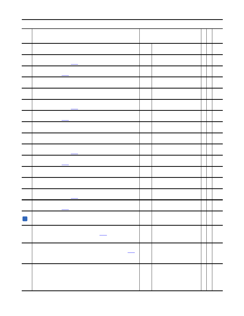
571
Trend In1 Real
Provides real input to the Trend 1. The Trending function samples this parameter for Trend Buffer 1, if bit 1 “In 1
Real” is set.
Default:
Min/Max:
0.0000
-/+2200000000.0000
Y
RW Real
572
Trend Out1 DInt
Displays the output for Trend Buffer 1, if the buffer is using integer data. This will equal the value of the
element, in Trend Buffer 1, specified by
[TrendBuffPointer].
Default:
Min/Max:
0
-/+2147483648
RO 32-bit
Integer
573
Trend Out1 Real
Displays the output for Trend Buffer 1, if the buffer is using real data. This will equal the value of the element,
in Trend Buffer 1, specified by
[TrendBuffPointer].
Default:
Min/Max:
0.0000
-/+2200000000.0000
RO Real
574
Trend In2 DInt
Provides integer input to the Trend 2. The Trending function samples this parameter for Trend Buffer 2, if bit 2
“In 2 Real” is cleared.
Default:
Min/Max:
0
-/+2147483648
Y
RW 32-bit
Integer
575
Trend In2 Real
Provides real input to the Trend 2. The Trending function samples this parameter for Trend Buffer 2, if bit 2 “In 2
Real” is set.
Default:
Min/Max:
0.0000
-/+2200000000.0000
Y
RW Real
576
Trend Out2 DInt
Displays the output for Trend Buffer 2, if the buffer is using integer data. This will equal the value of the
element, in Trend Buffer 2, specified by
[TrendBuffPointer].
Default:
Min/Max:
0
-/+2147483648
RO 32-bit
Integer
577
Trend Out2 Real
Displays the output for Trend Buffer 2, if the buffer is using real data. This will equal the value of the element,
in Trend Buffer 2, specified by
[TrendBuffPointer].
Default:
Min/Max:
0.0000
-/+2200000000.0000
RO Real
578
Trend In3 DInt
Provides integer input to the Trend 3. The Trending function samples this parameter for Trend Buffer 3, if bit 3
“In 3 Real” is cleared.
Default:
Min/Max:
0
-/+2147483648
Y
RW 32-bit
Integer
579
Trend In3 Real
Provides real input to the Trend 3. The Trending function samples this parameter for Trend Buffer 3, if bit 3 “In 3
Real” is set.
Default:
Min/Max:
0.0000
-/+2200000000.0000
Y
RW Real
580
Trend Out3 DInt
Displays the output for Trend Buffer 3, if the buffer is using integer data. This will equal the value of the
element, in Trend Buffer 3, specified by
[TrendBuffPointer].
Default:
Min/Max:
0
-/+2147483648
RO 32-bit
Integer
581
Trend Out3 Real
Displays the output for Trend Buffer 3, if the buffer is using real data. This will equal the value of the element,
in Trend Buffer 3, specified by
[TrendBuffPointer].
Default:
Min/Max:
0.0000
-/+2200000000.0000
RO Real
582
Trend In4 DInt
Provides integer input to the Trend 4. The Trending function samples this parameter for Trend Buffer 4, if bit 4
“In 4 Real” is cleared.
Default:
Min/Max:
0
-/+2147483648
Y
RW 32-bit
Integer
583
Trend In4 Real
Provides real input to the Trend 4. The Trending function samples this parameter for Trend Buffer 4, if bit 4 “In 4
Real” is set.
Default:
Min/Max:
0.0000
-/+2200000000.0000
Y
RW Real
584
Trend Out4 DInt
Displays the output for Trend Buffer 4, if the buffer is using integer data. This will equal the value of the
element, in Trend Buffer 4, specified by
[TrendBuffPointer].
Default:
Min/Max:
0
-/+2147483648
RO 32-bit
Integer
585
Trend Out4 Real
Displays the output for Trend Buffer 4, if the buffer is using real data. This will equal the value of the element,
in Trend Buffer 4, specified by
[TrendBuffPointer].
Default:
Min/Max:
0
-/+2200000000.0000
RO Real
586
IdsCmd Slew Rate
Defines the slew rate for the torque producing voltage (Vqs) regulator. The output variation is limited by one
count every Par 586 / 16 sec.
Notes: This value should not be changed. This parameter was added for firmware version 4.001.
Default:
Min/Max:
Units:
5.000
0.000/16.383
s
RW Real
587
SlipReg Err Lmt
Defines the error level at which the slip regulator input becomes active. When the error level reaches the value
specified in this parameter and the error count condition (specified in
[Err Count Lmt]) is met, the drive
control will transition from the slew rate limit mode to normal operation of the slip regulator.
Notes: This value should not be changed. This parameter was added for firmware version 4.001.
Default:
Min/Max:
0
+/-32767
RW 16-bit
Integer
588
VqsReg Err Lmt
Defines the error level at which the Flux Producing Voltage (Vqs) regulator input becomes active. When the
error level reaches the value specified in this parameter and the error count condition (specified in
[Err
Count Lmt]) is met, the drive control will transition from the slew rate limit mode to normal operation of the
Vqs regulator.
Notes: This value should not be changed. This parameter was added for firmware version 4.001.
Default:
Min/Max:
0
+/-32767
RW 16-bit
Integer
589
Err Count Lmt
Defines the control loop counts limit, where the counter counts up if the error level of the Vqs regulator input is
equal to the error level during Flux Producing Current (Ids) command Slew Rate operation. When the counter
exceeds the value of this parameter then the normal Vqs regulator operation becomes active. The same limit of
control loop counts is applied to the Slip Slew Rate operation, where the counter counts up if the error level of
the Slip regulator input is equal to the error level during Slip Slew Rate operation. When the counter exceeds
the value of this parameter then the normal Slip regulator operation becomes active.
Notes: This value should not be changed. This parameter was added for firmware version 4.001.
Default:
Min/Max:
0
+/-32767
RW 16-bit
Integer
No.
Name
Description
Values
Link
able
Re
ad
-Write
Da
ta
T
yp
e
A