Drive hardware configuration, Operation verification – Rockwell Automation 20D PowerFlex 700S AC Drives with Phase II Control Programming Manual User Manual
Page 208
208
Rockwell Automation Publication 20D-PM001C-EN-P - July 2013
Appendix E
ATEX Approved PowerFlex 700S, Phase II Drives in Group II Category (2) Applications with ATEX Approved Motors
Drive Hardware
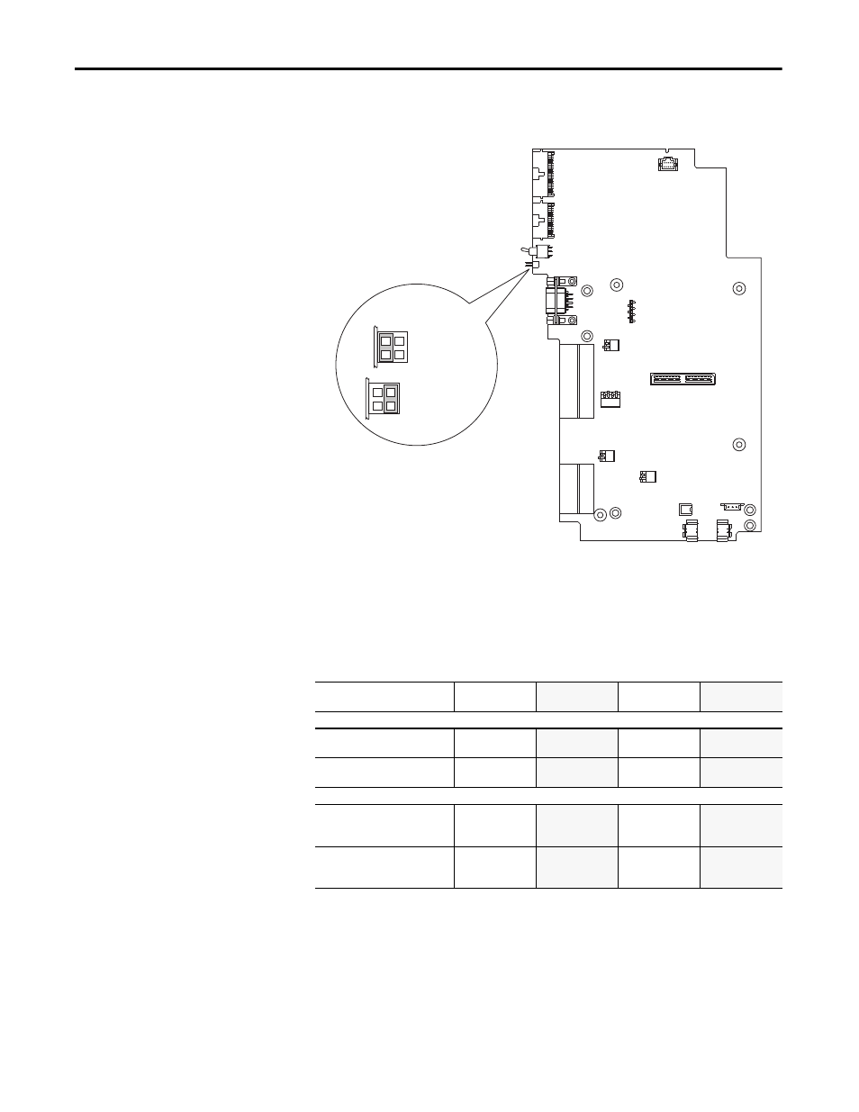
Configuration
Digital Input 6 must be configured as a Hardware Enable. Ensure that Jumper
P22 on the Main Control Board is set to HW Enable (Pins 2 and 4).`
Operation Verification
At regular intervals during the life of the machine check the protective system for
proper operation. Both channels shall be verified using the table below. How
frequently the protective system is checked is dependent on the safety analysis of
the machine section controlled by the drive.
= HW Enable
= No HW Enable
Jumper P22
1
2
3
4
1
2
3
4
Protective System Status
Drive In
Safe State
Drive In
Safe State
Drive In
Safe State
Drive Able
To Run
Channel Operation
Safe-Off Option
Terminals 1 & 2
No Power Applied
Power Applied
No Power Applied
Power Applied
PowerFlex 700S Phase II
Enable Input
No Power Applied
No Power Applied
Power Applied
Power Applied
Description For Verification
Safe-Off Option
Monitor Contact
Terminals 3 & 4
Closed
Open
Closed
Open
PowerFlex 700S Phase II
Drive Inhibits
Param. 156, Bits 1 & 16
Bit 16 = 1
Bit 1 = 1
Bit 16 = 0
Bit 1 = 1
Bit 16 = 1
Bit 1 = 0
Bit 16 = 0
Bit 1 = 0