Par 780, Par 781, Par 782 – Rockwell Automation 20D PowerFlex 700S AC Drives with Phase II Control Programming Manual User Manual
Page 108: Par 777
108
Rockwell Automation Publication 20D-PM001C-EN-P - July 2013
Chapter 2
Programming and Parameters
770
PositReg Integ
Sets position regulator integral gain as measured from position error to velocity reference. It has gain units of
(per unit velocity/sec) / (per unit position) and is unit compatible with
[PositReg P Gain]. An integral
gain of 25 means that a per unit position error of 0.1 sec will effect a 2.5 P.U. speed change per sec.
Note: 1 per unit position is the distance traveled in 1 sec. at base motor speed.
Default:
Min/Max:
Units:
4.0000
0.0000/1000.0000
/S
2
Y
RW Real
771
PositReg Droop
Position Droop limits the low frequency gain of the position regulators integral channel to a value of (1/droop). It
provides a means to fine tune the stability for load mounted feedback devices where lost motion may cause a
problem. Typically, position droop will have a value that is less than (1/position gain), perhaps even zero for
tightly coupled loads. Position droop has a gain value of (per unit position) / (per unit speed). Note: 1 per unit
position is the distance traveled in 1 sec. at base motor speed.
Default:
Min/Max:
0.0000
0.0000/0.2500
Y
RW Real
772
XReg Integ LoLim
The negative limit of the position regulator integral gain.
Default:
Min/Max:
Units:
Scale:
-176.4000
-14112.0000/0.0000
rpm
[Motor NP RPM] = 1.0 P.U.
Y
RW Real
773
XReg Integ HiLim
The positive limit of the position regulator integral gain.
Default:
Min/Max:
Units:
Scale:
176.4000
0.0000/14112.0000
rpm
[Motor NP RPM] = 1.0 P.U.
Y
RW Real
774
XReg Integ Out
The output of the position regulator integral channel after application of the limits. This output is set to zero if
the integral gain is set to zero or the integrator is not enabled.
Default:
Min/Max:
Units:
Scale:
0
-/+14112.0000
rpm
[Motor NP RPM] = 1.0 P.U.
RO Real
775
XReg Spd LoLim
The negative speed limit of total position regulator output. Point to point mode uses this parameter to set the
reverse speed reference.
Default:
Min/Max:
Units:
Scale:
-176.4000
-14112.0000/0.0000
rpm
[Motor NP RPM] = 1.0 P.U.
Y
RW Real
776
XReg Spd HiLim
The positive speed limit of total position regulator output. Point to point mode uses this parameter to set the
forward speed reference.
Default:
Min/Max:
Units:
Scale:
176.4000
0.0000/14112.0000
rpm
[Motor NP RPM] = 1.0 P.U.
Y
RW Real
777
PositionFdbk Sel
Enter a value to select the position control feedback device. The feedback device used for position control may be
an independent selection from the motor speed control feedback device in
[Mtr Fdbk Sel Pri] or
[Mtr Fdbk Sel Alt]. If the position feedback is to be the same as the motor feedback, select option 3 “Motor Fdbk”.
This option will set the selected feedback of Par 222 [Motor Fdbk Sel Pri] or Par 223 [Mtr Fdbk Sel Alt] as the
position regulators position feedback.
Notes: Options 5 and 6 are only available when compatible feedback option card is installed. This parameter was
changed to non-linkable for firmware version 3.001.
Default:
Options:
0 =
0 =
1 =
2 =
3 =
4 =
5 =
6 =
“Encoder 0”
“Encoder 0”
7 = “SL DirIntRx0”
“Encoder 1”
8 = “SL DirIntRx1”
“Reserved”
9 = “SL DirIntRx2”
“Mtr Fdbk Pri”
10 = “SL DirIntRx3”
“Motor Sim”
“FB Opt Port0”
“FB Opt Port1”
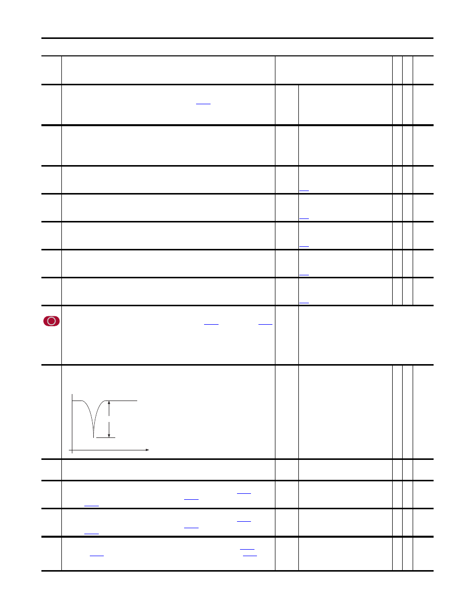
778
X Notch Attenu
Sets the depth for the Position Notch Filter. Attenuation is the ratio of the output to the input at the notch
frequency. An attenuation of 30 means that the notch output is 1/30th of the input at the specified frequency.
Calculation: Attenuation = Input / Output
Default:
Min/Max:
50
0/500
Y
RW Real
779
X Notch FiltFreq
Sets the center frequency of the Position Notch Filter.
Default:
Min/Max:
Units:
0.0
0.0/500.0
Hz
Y
RW Real
780
PositDetct1 Stpt
Provides the set point for Position Watch 1. Position Watch 1 is enabled and configured with
[Position
Control] bits 16 & 17. Position Watch 1 compares this value with
[Posit Dect1 In] and sets bit 8 “Posit
[Position Status] when the appropriate condition is satisfied.
Default:
Min/Max:
0
-/+2147483648
Y
RW 32-bit
Integer
781
PositDetct2 Stpt
Provides the set point for Position Watch 2. Position Watch 2 is enabled and configured with
[Position
Control] bits 18 & 19. Position Watch 2 compares this value with
[Posit Dect2 In] and sets bit 9 “Posit
[Position Status] when the appropriate condition is satisfied.
Default:
Min/Max:
0
-/+2147483648
Y
RW 32-bit
Integer
782
In Posit BW
Sets the overall bandwidth of the In Position detector. The detector sets bit 10 “In Position” of
[Position
Status], when
[Position Error] is within this bandwidth for a sufficient time, specified by
[In Posit
Dwell]. A modest hysteresis count is added to the position bandwidth after the position error is within specified
limits.
Default:
Min/Max:
200
0/1000000
Y
RW 32-bit
Integer
No.
Name
Description
Values
Link
able
Re
ad
-Write
Da
ta
T
yp
e
Freq (Hz)
Attenuation