Rockwell Automation 20D PowerFlex 700S AC Drives with Phase II Control Programming Manual User Manual
Page 62
62
Rockwell Automation Publication 20D-PM001C-EN-P - July 2013
Chapter 2
Programming and Parameters
284
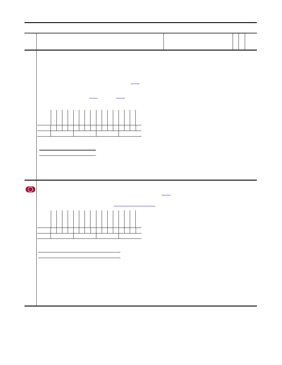
Sleep Control
Status of the Sleep-Wake function.
• Bit 0 “Enable” when set, Sleep-Wake mode is enabled.
• Bit 1 “Analog Ref 0” when set, indicates that analog input 1 is used for Sleep mode control.
• Bit 2 “Analog Ref 1” when set, indicates that analog input 2 is used for Sleep mode control.
• Bit 3 “Mode 0” when set, direct control is used.
• Bit 4 “Mode 1” when set, inverted control is used.
• Bits 5…7 “State x” indicate the Sleep-Wake mode state that is currently active. See Table 284A: Sleep-Wake Mode Active State below.
• Bit 8 “Digin Cnflct” when set indicates that a digital input conflict exists. See Par
[Sleep-Wake Mode] for details on digital input programming for the Sleep-Wake function.
• Bit 9 “Stop Latch” when set, a Stop command is being issued from the sleep mode.
• Bit 10 “Start Latch” Not used.
• Bit 11 “Not Running” when set, the drive is not running.
• Bit 12 “Level Cnflct” when set, the value of
[Wake Level] or
[Sleep Level] is outside the Min/Max range of the assigned analog input (mA or V). Or, if in direct mode, the value of
[Sleep Level] is greater than the value of [Wake Level].
Note: This parameter was added with firmware version 5.002.
285
Linear1 Config
Used to configure a linear encoder when a Multi Device Interface (MDI) feedback card is installed.
Note: This parameter was added for firmware version 2.003.
• Bit 5 “Direction” - Setting this bit to “1” inverts the count (up/down) direction of the linear feedback position
[FB Opt1 Posit]. If [FB Opt1 Posit] has been counting up for forward feedback
sensor travel then setting this bit will cause [FB Opt1 Posit] to count down. The opposite behavior will occur when the sensor moves in the other direction.
• Bit 6 “Stahl Linear” - Setting this bit to “1” indicates to the MDI card that a Stahl type linear device is being used. It this bit is set to “0” then a Temposonics linear device is being used.
• Bits 10 - 12 form a 3 bit moving average filter sampling rate. See
Table 285A: Sample Rate Bit Settings
No.
Name
Description
Values
Link
able
Re
ad
-Write
Da
ta
T
yp
e
Options
un
us
ed
3
un
us
ed
2
un
us
ed
1
Le
ve
l C
nf
lc
t
Not Running
Star
t L
at
ch
St
op La
tc
h
Di
gi
n C
nf
lct
Sta
te
2
Sta
te
1
Sta
te
0
Mode 1
Mode 0
Analog Ref 1
Analog Ref 0
Enable
Default
x
x
x
0
0
0
0
0
0
0
0
0
0
0
0
0
Bit
15 14 13 12 11 10 9
8
7
6
5
4
3
2
1
0
0 = False
1 = True
Table 284A: Sleep-Wake Mode Active State
Bit
7
6
5 Active Mode
0
0
0 Drive is powering up
0
0
1 Drive is asleep
0
1
0 Drive is waiting
0
1
1 Drive is awake
Options
Re
se
rv
ed
Re
se
rv
ed
Re
se
rv
ed
Op1
Smp
lR
t b3
Op1
Smp
lR
t b2
Op1
Smp
lR
t b1
Re
se
rv
ed
Re
se
rv
ed
Re
se
rv
ed
Stahl Linear
Dir
ec
tio
n
Re
se
rv
ed
Re
se
rv
ed
Re
se
rv
ed
Re
se
rv
ed
Re
se
rv
ed
Default
x
x
x
0
1
1
x
x
x
0
0
x
x
x
x
x
Bit
15 14 13 12 11 10 9
8
7
6
5
4
3
2
1
0
0 = False
1 = True
Table 285A: Sample Rate Bit Settings
Bit 12 11 10 Exponent Value ‘n’ Filter Sample Size = 2
n
0
0
0 0
1
0
0
1 1
2
0
1
0 2
4
0
1
1 3
8 (Default)
1
0
0 4
16
1
0
1 5
32
1
1
0 6
64
1
1
1 7
127