Rockwell Automation 20D PowerFlex 700S AC Drives with Phase II Control Programming Manual User Manual
Page 89
Rockwell Automation Publication 20D-PM001C-EN-P - July 2013
89
Programming and Parameters
Chapter 2
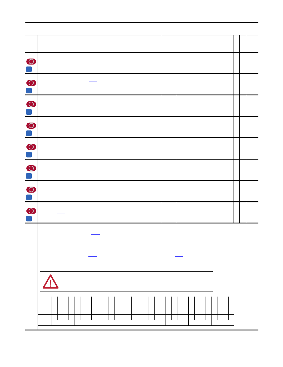
No.
Name
Description
Values
Li
nk
ab
le
Re
ad
-W
ri
te
Da
ta
T
ype
502 Rotor
Resistance
Displays rotor resistance, as determined by the auto-tune procedure. Scaled to percent of rated motor
impedance. Do not change this value.
Default:
Min/Max:
Units:
Scale:
1.00
0.00/100.00
%
100 = 8192
RW 16-bit
Integer
503 Current
Reg
BW
Sets the bandwidth for the current regulator.
[PWM Frequency] limits the maximum value. Reducing
the value reduces current regulator over-shoot.
Default:
Min/Max:
Units:
600
100/30000
rad/s
RW 16-bit
Integer
504
PM AbsEncd Offst
Determined by auto-tune procedure.
Default:
Min/Max:
0
0/65535
RW 16-bit
Integer
505
PM TestWait Time
Defines the time interval used for the automated measurement of
[PM AbsEncd Offst] for a Permanent
Magnet (PM) motor.
Default:
Min/Max:
Units:
2000
500/5000
ms
RW 16-bit
Integer
506
PM Test Idc Ramp
Defines the ramp rate of the Flux Producing (d-axis) current reference that is used for the automated
measurement of
[PM AbsEncd Offst] for a Permanent Magnet (PM) motor.
Default:
Min/Max:
Units:
Scale:
0.1
0.0/195.3
%/ms
x 10
RW 16-bit
Integer
507
PM Test FreqRamp
Defines the ramp rate of the frequency reference that is used for the automated measurement of
[PM
AbsEncd Offst] for a Permanent Magnet (PM) motor.
Default:
Min/Max:
Units:
Scale:
0.1
0.0/195.3
%/ms
x 10
RW 16-bit
Integer
508
PM Test Freq Ref
Defines the frequency reference that is used for the automated measurement of
[PM AbsEncd Offst] for
a Permanent Magnet (PM) motor.
Default:
Min/Max:
Units:
Scale:
10.0
-/+799.9
%
x 10
RW 16-bit
Integer
509
PM Test I Ref
Defines the amplitude of the Flux Producing (d-axis) current reference that is used for the automated
measurement of
[PM AbsEncd Offst] for a Permanent Magnet (PM) motor.
Default:
Min/Max:
Units:
Scale:
30.0
0.0/799.9
%
x 10
RW 16-bit
Integer
510
FVC Mode Config
Configures Field Oriented Control (FOC) operation.
• Bit 4 “SlipTuneDone” when set, the value in
[Rated Slip Freq] is used as the slip gain before the slip regulator becomes active, after power is cycled, or when the drive is reset by the
system. When the Slip Tune is completed, this bit will be automatically be set and Par 486 will be updated.
• Bit 7 “Ids Comp En” setting this bit runs the Ids test, to establish the initial flux current level for the motor, and the inertia test (even if already run).
• Bit 12 “SlipRsCompEn” when set, the stator resistance will be compensated based on the output of the slip regulator.
• Bit16 “ManuCurOffst” when set,
[Iu Offset] is used as the phase U current feedback offset value and
[Iw Offset] is used as the phase W current feedback offset value. When this bit
is not set (default) the phase U and W current feedback offset values are automatically updated when the drive is in a stop condition except during the first 10 seconds of the stop condition.
• Bit17 “ManuVltOffst” when this bit is set,
[Vuv Fdbk Offset] is used as the UV voltage feedback offset value and
[Vvw Fdbk Offset] is used as the VW voltage feedback offset value.
• Bit 23 “SyncTrans En” when set (default), the synchronous transfer algorithm using voltage feedback data is active.
Notes: Bit changes were made for firmware version 2.003. Bits 10 and 11 were added for firmware version 3.001. Changed bit 3 from “Reserved” to “FastFluxDsbl” for firmware version 3.003. Added
bits 4, 7, 12, 16, 17 and 23 for firmware version 4.001.
A
A
A
A
A
A
A
A
ATTENTION: Do not modify this parameter. Motor/Drive instabilities and damage may result.
Options
Re
se
rv
ed
Re
se
rv
ed
Re
se
rv
ed
Re
se
rv
ed
Re
se
rv
ed
Re
se
rv
ed
Re
se
rv
ed
Re
se
rv
ed
Sy
nc
Tr
an
s En
Sr
Ls
s Rd
Th
ru
Vl
tM
in
or
Lp
En
So
ft
AdptG
ain
Re
se
rv
ed
Re
se
rv
ed
Ma
nuVl
tO
ffs
t
ManuC
urO
ffs
t
Lw
SpdRflc
tW
v
Slip Reg En
Sl
ipG
ain Es
t
Sl
ipR
sC
omp
En
SlipPr
lo
adEn
SlipS
lew
Rt
En
Re
flW
av
eC
omp
BusGai
n C
om
p
Ids
C
om
p En
Flu
x Reg
Us
e
Flu
x Reg
E
n
Slip
Tu
neD
one
Fa
st
Fl
ux
Ds
bl
Re
se
rv
ed
Re
se
rv
ed
Re
se
rv
ed
Default
x
x
x
x
x
x
x
x
1
0
1
0
x
x
0
0
0
1
1
0
0
0
1
1
0
1
1
0
0
x
x
x
Bit
31 30 29 28 27 26 25 24 23 22 21 20 19 18 17 16 15 14 13 12 11 10 9
8
7
6
5
4
3
2
1
0
0 = False
1 = True