Rockwell Automation 20D PowerFlex 700S AC Drives with Phase II Control Programming Manual User Manual
Page 82
82
Rockwell Automation Publication 20D-PM001C-EN-P - July 2013
Chapter 2
Programming and Parameters
449
SrLss FreqReg Ki
Sets the integral gain of the Frequency Regulator, which estimates motor speed when sensorless feedback is
selected. Do not change this value.
Default:
Min/Max:
250
0/32767
RW 16-bit
Integer
450
SrLss FreqReg Kp
Sets the proportional gain of the Frequency Regulator, which estimates motor speed when sensorless
feedback is selected. Do not change this value.
Default:
Min/Max:
350
0/32767
RW 16-bit
Integer
453 Iu
Offset
Sets the current offset correction for the phase U current. This value is set automatically when the drive is not
running and Motor Control (MC) is not faulted. Do not change this value.
Default:
Min/Max:
0
-/+32767
RW 16-bit
Integer
454 Iw
Offset
Sets the current offset correction for the flux producing (d-axis) current regulator. This value is set
automatically when the drive is not running and Motor Control (MC) is not faulted. Do not change this value.
Default:
Min/Max:
0
-/+32767
RW 16-bit
Integer
456
MC Build Number
Displays the build number of the drive's Motor Control (MC) software.
Default:
Min/Max:
0
0/65535
RO
16-bit
Integer
457
MC Firmware Rev
Displays the major and minor revision levels of the drive's Motor Control (MC) software. Changed all values to
three decimal places for firmware version 4.001.
Default:
Min/Max:
Scale:
0.000
0.000/655.350
x 10
RO
16-bit
Integer
459
IdsCompCoeff Mot
Defines the flux producing current (Ids) command compensation coefficient used during motoring. When this
parameter is set to 1024 the amount of compensation, which is proportional to torque producing current (Iqs)
command, is 100% of the rated flux current at 1 P.U. of Iqs command when the torque producing voltage
(Vqs) regulator is off and
[FVC Mode Config], bit 7 “Ids Comp En” = “1”. No Ids command
compensation will be applied when Par 510 [FVC Mode Config], bit 7 = “0”.
Notes: Refer to “Ids Compensation Coefficient Set Up” in the PowerFlex 700S with Phase II Control Reference
Manual, publication
, for more information. This parameter was added for firmware version
4.001.
Default:
Min/Max:
0
+/-32767
RW 16-bit
Integer
460
IdsCompCoeff Reg
Defines the flux producing current (Ids) command compensation coefficient used during regeneration. When
this parameter is set to 1024 the amount of compensation, which is proportional to torque producing current
(Iqs) command, is 100% of the rated flux current at 1 P.U. of Iqs command when the Vqs regulator is off and
[FVC Mode Config], bit 7 “Ids Comp En” = “1”. No Ids command compensation will be applied when
Par 510 [FVC Mode Config], bit 7 = “0”.
Notes: Refer to “Ids Compensation Coefficient Set Up” in the PowerFlex 700S with Phase II Control Reference
Manual, publication
, for more information. This parameter was added for firmware version
4.001.
Default:
Min/Max:
0
+/-32767
RW 16-bit
Integer
461
SlipReg Off Iqs
Defines the torque producing current (Iqs) reference level below which the slip regulator turns off, when the
slip regulator turn off point is defined as ((Par 461 / 10) + 5) % of the rated Iqs reference. The slip regulator
turn on point is defined as ((Par 461 / 10) + 10) % of the rated Iqs reference with the condition of the Vqs
regulator is turned on.
Note: This parameter was added for firmware version 4.001.
Default:
Min/Max:
200
+/-32767
RW 16-bit
Integer
462
VqsReg Off Freq
Defines the output frequency level below which the Vqs regulator turns off, when the Vqs regulator turn off
point is defined as (Par 462 / 10) % of the rated motor frequency. The Vqs regulator turn on point is defined as
((Par 462 / 10) + 2) % of the rated motor frequency.
Note: This parameter was added for firmware version 4.001.
Default:
Min/Max:
150
0/1000
RW 16-bit
Integer
463
MC Diag Error 1
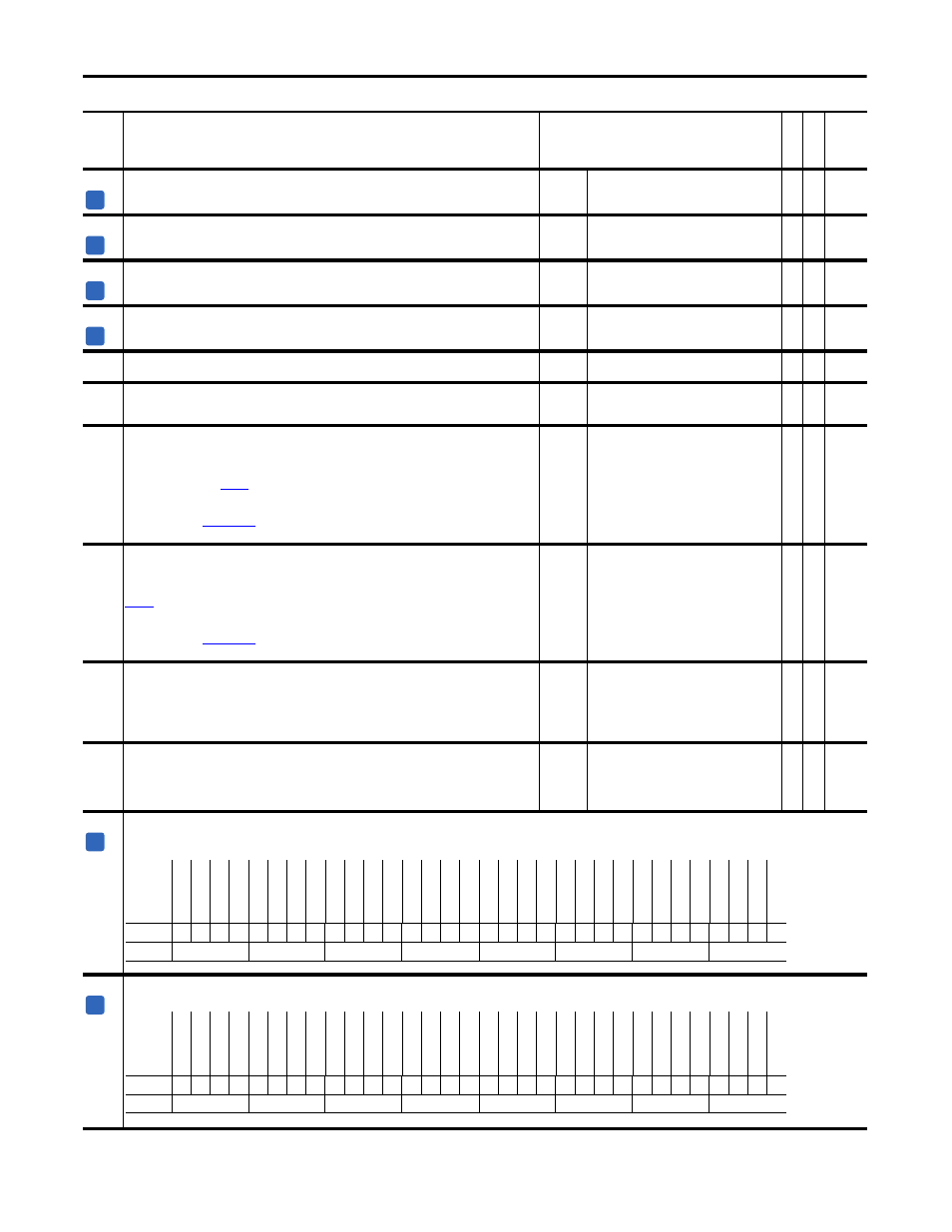
Displays the first diagnostic error encountered by the Motor Control (MC). Errors appear in this parameter in the order in which they occurred.
Note: Bits 7 & 8 have been changed to “Ground Fault” for firmware version 2.004.
464
MC Diag Error 2
Displays the second diagnostic error encountered by the Motor Control (MC). Errors appear in this parameter in the order in which they occurred.
No.
Name
Description
Values
Link
able
Re
ad
-Write
Da
ta
T
yp
e
A
A
A
A
A
Options
Re
se
rv
ed
Re
se
rv
ed
Re
se
rv
ed
Re
se
rv
ed
Re
se
rv
ed
Re
se
rv
ed
Re
se
rv
ed
Re
se
rv
ed
Re
se
rv
ed
Re
se
rv
ed
Re
se
rv
ed
Re
se
rv
ed
Ne
g P
ara
me
tr
N
ot Rota
tin
g
N
ot Rota
tin
g
Re
se
rv
ed
Re
se
rv
ed
WP
-V
NOn-
W
cur
WP
-UNOn-U
,W
VP
-W
NOn-
W
cur
VP
-UNOn-Uc
ur
UP
-W
NOn-U
,W
UP
-V
NOn-Ucur
Gr
ound F
ault
Gr
ound F
ault
UP
,V
Pd
evShr
t
UP
,W
Pd
evShr
t
VP
,WP
devS
hr
t
UN,VN
devShr
t
UN,WN
devShr
t
VN,WN
de
vShr
t
Vb
us
R
an
ge
Default
x
x
x
x
x
x
x
x
x
x
x
x
0
0
0
x
x
0
0
0
0
0
0
0
0
0
0
0
0
0
0
0
Bit
31 30 29 28 27 26 25 24 23 22 21 20 19 18 17 16 15 14 13 12 11 10 9
8
7
6
5
4
3
2
1
0
0 = False
1 = True
A
Options
Re
se
rv
ed
Re
se
rv
ed
Re
se
rv
ed
Re
se
rv
ed
Re
se
rv
ed
Re
se
rv
ed
Re
se
rv
ed
Re
se
rv
ed
Re
se
rv
ed
Re
se
rv
ed
Re
se
rv
ed
Re
se
rv
ed
Re
se
rv
ed
Re
se
rv
ed
Negativ
e W
r
Re
se
rv
ed
Re
se
rv
ed
WP
-V
N
O
n-
Vv
w
WP
U
N
-V
uv
,V
vw
VP
-W
N
O
n-
Vv
w
VP
-U
N
O
n-
Vu
v
UP
WN-
Vuv
,V
vw
UP
-V
NO
n-
Vu
v
Re
se
rv
ed
Re
se
rv
ed
Re
se
rv
ed
Re
se
rv
ed
Re
se
rv
ed
Re
se
rv
ed
Re
se
rv
ed
Re
se
rv
ed
Sen
sO
fst
Rn
ge
Default
x
x
x
x
x
x
x
x
x
x
x
x
x
x
0
x
x
0
0
0
0
0
0
x
x
x
x
x
x
x
x
0
Bit
31 30 29 28 27 26 25 24 23 22 21 20 19 18 17 16 15 14 13 12 11 10 9
8
7
6
5
4
3
2
1
0
0 = False
1 = True