Rockwell Automation 20D PowerFlex 700S AC Drives with Phase II Control Programming Manual User Manual
Page 102
102
Rockwell Automation Publication 20D-PM001C-EN-P - July 2013
Chapter 2
Programming and Parameters
698
Motn Posit Cmmd
Position command input from the Motion Planner. This is linked as the source to the interpolator’s Course Position
Target.
Default:
Min/Max:
0
-/+2147483648
RO 32-bit
Integer
699
Motn Speed Cmmd
Speed command input from the Motion Planner.
Default:
Min/Max:
Units:
0.0000
-/+8.0000 P.U.
P.U.
RO Real
700
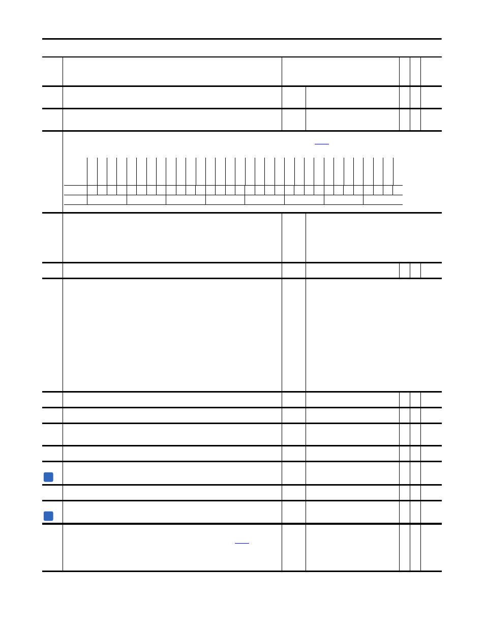
Motn Posit Sync
Synchronization input signal from the Motion Planner. Pulse received once per coarse update period. This is linked as the course to
[Interp SynchInput].
Note: Bits 2 - 4 have been changed to “Reserved” for firmware version 2.004.
701
FdbkAxis FdbkSel
Selection for the Motion Feedback Only Axis feedback source.
Note: Options 5 and 6 are only available when compatible feedback option card is installed.
Note: Bit 11 “SL Buff Rx10” was added for firmware version 4.001.
Default:
Options:
0 =
0 =
1 =
2 =
3 =
4 =
5 =
“Encoder 0”
“Encoder 0”
6 = “FB Opt Port1”
“Encoder 1”
7 = “SL DirIntRx0”
“Reserved”
8 = “SL DirIntRx1”
“Reserved”
9 = “SL DirIntRx2”
“Motor Sim”
10 = “SL DirIntRx3”
“FB Opt Port0”
11 = “SL Buff Rx10”
702
FdbkAxis FdbkVal
Present value of the selected feedback for the Motion Feedback Only Axis.
Default:
Min/Max:
0
-/+2147483648
RO 32-bit
Integer
703
Motn TP Select
Selector for diagnostic Test point relating to Motion functionality.
Default:
Options:
0 =
0 =
1 =
2 =
3 =
4 =
5 =
6 =
7 =
8 =
9 =
10 =
11 =
12 =
13 =
14 =
15 =
“SrvoAxisCnfgxe”
“SrvoAxisCnfg”
16 = “CST Upper”
“SrvoAxisUnwd”
17 = “FBonlyFbkRaw”
“Marker Dist”
18 = “Reserved”
“HomeEvent X”
19 = “I/O Rx Seq#”
“Watch Posit”
20 = ”I/O Rx Msg#”
“Home Posit”
21 = 'I/O Tx Msg#”
“SrvoMRP Ofst”
22 = “Syn Rx Seq#”
“SrvoAct Ofst”
23 = “Syn Rx Msg#”
“PositRegis1”
24 = “Syn Tx Msg#”
“PositRegis2”
25 = “Evt Rx Seq#”
“FdbkAxisCnfg”
26 = “Evt Rx Msg#”
“FdbkAxisUnwd”
27 = “Evt Tx Msg#”
“FdbkMRP Ofst”
28 = “Asy Rx Seq#”
“FdbkAct Ofst”
29 = “Asy Rx Msg#”
“TimeEvntStat”
30 = “Asy Tx Msg#”
“CST Lower”
31 = “Reset Msg#”
704
Motn TP Value
Data for diagnostic Test point relating to Motion functionality.
Default:
Min/Max:
0
-/+2147483648
RO 32-bit
Integer
705
Motn RotaryCmmd
Position command input from the Motion Planner to the ServoAxis when configured in rotary mode.
Default:
Min/Max:
0
0/4294967295
RO 32-bit
Integer
706
MotnUnwdTurnCmmd
Position unwind turns command input from the Motion Planner to the Servo Axis when configured in rotary
mode.
Default:
Min/Max:
0
-/+32767
RO 16-bit
Integer
707
SrvoAxis RotFdbk
Position feedback output to the Motion Planner for the Servo Axis when configured in rotary mode.
Default:
Min/Max:
0
0/4294967295
RO 32-bit
Integer
708
SrvoAxisUnwdFdbk
Position unwind feedback output to the Motion Planner for the Servo Axis when configured in rotary mode.
Default:
Min/Max:
0
-/+32767
RO 16-bit
Integer
709
FdbkAxis RotFdbk
Positon feedback output to the Motion Planner for the Feedback Only Axis when configured in rotary mode.
Default:
Min/Max:
0
0/4294967295
RO 32-bit
Integer
710
FdbkAxisUnwdFdbk
Position unwind feedback output to the Motion Planner for the Feedback Only Axis when configured in rotary
mode.
Default:
Min/Max:
0
-/+32767
RO 16-bit
Integer
711
MotnCnfgErrParam
Identifies a parameter that is not configured properly for a motion connection to be accepted. The parameter
identified could either have a wrong value or an incorrect link. When bit 0 “Config OK” of
[Motn Cnct
Status] is set, then this parameter contains the parameter number of an incorrectly configured parameter. If more
than one parameter is incorrectly configured, each is displayed in turn after the previously identified parameter is
fixed. If there are no configuration problems relating to Motion, then this parameter contains a value of zero and
the bit 0 “Config OK” of parameter 690 [Motn Cnct Status] is cleared.
Default:
Min/Max:
0
0/65535
RO 16-bit
Integer
No.
Name
Description
Values
Link
able
Re
ad
-Write
Da
ta
T
yp
e
Options
Re
se
rv
ed
Re
se
rv
ed
Re
se
rv
ed
Re
se
rv
ed
Re
se
rv
ed
Re
se
rv
ed
Re
se
rv
ed
Re
se
rv
ed
Re
se
rv
ed
Re
se
rv
ed
Re
se
rv
ed
Re
se
rv
ed
Re
se
rv
ed
Re
se
rv
ed
Re
se
rv
ed
Re
se
rv
ed
Re
se
rv
ed
Re
se
rv
ed
Re
se
rv
ed
Re
se
rv
ed
Re
se
rv
ed
Re
se
rv
ed
Re
se
rv
ed
Re
se
rv
ed
Re
se
rv
ed
Re
se
rv
ed
Re
se
rv
ed
Re
se
rv
ed
Re
se
rv
ed
Re
se
rv
ed
Sy
nc
Da
ta
Ac
tv
Sy
nc
Pu
ls
e
Default
x
x
x
x
x
x
x
x
x
x
x
x
x
x
x
x
x
x
x
x
x
x
x
x
x
x
x
x
x
x
0
0
Bit
31 30 29 28 27 26 25 24 23 22 21 20 19 18 17 16 15 14 13 12 11 10 9
8
7
6
5
4
3
2
1
0
0 = False
1 = True
A
A