Rockwell Automation 20D PowerFlex 700S AC Drives with Phase II Control Programming Manual User Manual
Page 57
Rockwell Automation Publication 20D-PM001C-EN-P - July 2013
57
Programming and Parameters
Chapter 2
263
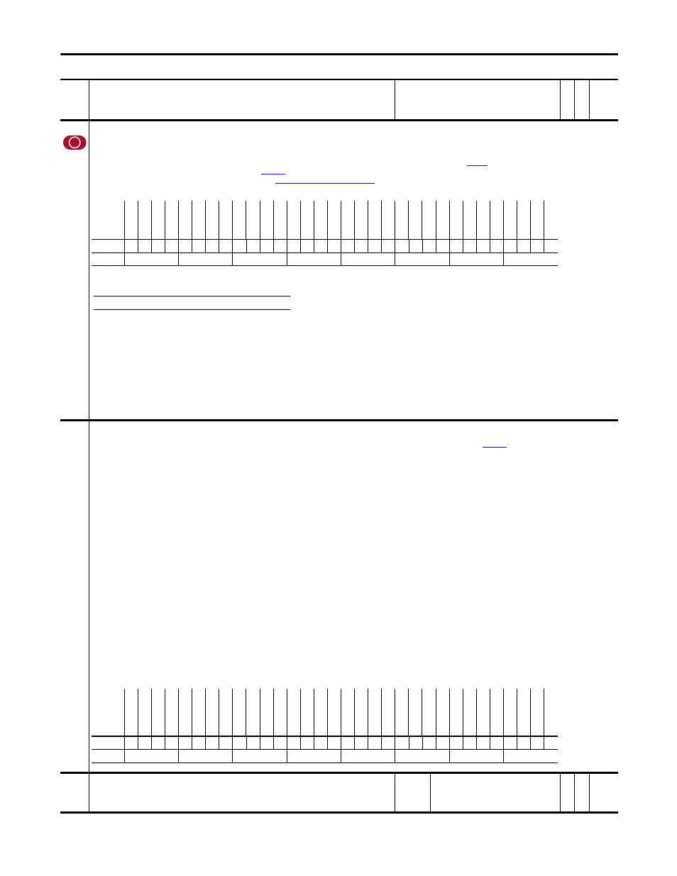
Heidenhain0 Cnfg
Configures the Heidenhain Encoder Feedback Option.
• Bit 5 “Direction” determines the counting direction. Set to “0” to count up or forward. Set to “1” to count in reverse or down.
• Bit 6 “SW Reset” setting this bit to “1” resets and restarts the option card.
• Bit 7 “VM Direction” determines the direction of the encoder pulse output from the Heidenhain option card when bit 6 “VrtlMasterEn” of
[Heidn Encdr Type] is set. When this bit is off, =
“0”, the direction of the encoder pulse output is the same as
[Heidn VM Pos Ref], and the reverse of Par 1155 when this bit is set, = “1”.
• Bits 10 -12 form a 3 bit moving average filter sampling rate. (See
Table 263A: Sample Rate Bit Settings
).
Notes: This parameter was added for firmware version 2.003. This parameter was changed to non-linkable for firmware version 3.001. Added bit 7 for firmware version 4.001.
264
Heidenhain0 Stat
Indicates fault and alarm statuses on the Heidendhain encoder feedback option card and Endat communication.
• Bit 0 “VM Enc Out” when set, indicates that the encoder output from the Heidenhain option card is the virtual encoder position determined by
[Heidn VM Pos Ref].
• Bit 1 “Emul Enc Out” when set, indicates that the encoder output from the Heidenhain option card is the emulated encoder position determined by the connected Heidenhain encoder.
• Bit 5 “Sig Amplitud” indicates that the signal amplitude is insufficient or too large.
• Bit 6 “Quadrate Er” indicates that there is a signal quadrature error.
• Bit 7 “Open Wire” indicates an open wire fault.
• Bit 8 “VoltageLvlEr” indicates that the operating voltage is too high or too low.
• Bit 9 “PowerSup Er” indicates the failure of the power supply.
• Bit 10 “PowerUpDiag Er” indicates the option board failed its power-up diagnostic test.
The pattern on the FPGA must be identical to the pattern written from the DSP, or the board status test will fail.
• Bit 11 “MsgChecksum Er” indicates a message checksum fault.
The check sum associated with the Endat communication device must be correct and acknowledged by the feedback option card.
• Bit 12 “Time Out Err” indicates an Endat time-out fault.
• Bit 13 “PPR Error” indicates an encoder PPR setting mismatch fault.
• Bit 14 “Bootup Error” indicates an Endat boot-up fault.
• Bit 15 “FW VersionEr” indicates that the firmware version of the encoder does not match the firmware version of the Heidenhain option card in the drive.
• Bit 16 “LightSrc Er” indicates an Endat light source fault.
• Bit 17 “Sig Amplitud” indicates an Endat signal amplitude fault.
• Bit 18 “PstvValue Er” indicates an Endat positive value fault.
• Bit 19 “Over Voltage” indicates an Endat over voltage fault.
• Bit 20 “Undr Voltage” indicates an Endat under voltage fault.
• Bit 21 “Over Current” indicates an Endat over current fault.
• Bit 24 “FrqExced Alm” indicates an Endat frequency exceeded alarm.
• Bit 25 “Temprtr Alm” indicates an Endat temperature exceeded alarm.
• Bit 26 “LghtCtrl Alm” indicates an Endat limit of light control alarm.
• Bit 28 “RefPoint Alm” indicates an Endat reference point alarm.
Notes: This parameter was added for firmware version 2.003. Bit 14 was changed from “Endat BootEr” to “Bootup Error” and bit 15 “FW VersionErr” is new for firmware version 3.001. Bits 0 and 1
were added for firmware version 4.001.
265
Heidn Mkr Offset
Configures marker offset values for the Heidenhain Encoder Feedback Option. The marker offset is specified
within one revolution.
Note: This parameter was added for firmware version 2.003.
Default:
Min/Max:
0.0000
0.0000/4294967295
Y
RW 32-bit
Integer
No.
Name
Description
Values
Link
able
Re
ad
-Write
Da
ta
T
yp
e
Options
Res
er
ve
d
Res
er
ve
d
Res
er
ve
d
Res
er
ve
d
Res
er
ve
d
Res
er
ve
d
Res
er
ve
d
Res
er
ve
d
Res
er
ve
d
Res
er
ve
d
Res
er
ve
d
Res
er
ve
d
Res
er
ve
d
Res
er
ve
d
Res
er
ve
d
Res
er
ve
d
Res
er
ve
d
Res
er
ve
d
Res
er
ve
d
SmplR
at
e bt2
SmplR
at
e bt1
SmplR
at
e bt0
Res
er
ve
d
Res
er
ve
d
VM D
ire
ct
ion
SW Re
se
t
Di
rec
tio
n
Res
er
ve
d
Res
er
ve
d
Res
er
ve
d
Res
er
ve
d
Res
er
ve
d
Default
x
x
x
x
x
x
x
x
x
x
x
x
x
x
x
x
x
x
x
0
1
1
x
x
0
0
0
x
x
x
x
x
Bit
31 30 29 28 27 26 25 24 23 22 21 20 19 18 17 16 15 14 13 12 11 10 9
8
7
6
5
4
3
2
1
0
0 = False
1 = True
Table 263A: Sample Rate Bit Settings
Bit 12 11 10 Exponent Value ‘n’ Filter Sample Size = 2
n
0
0
0 0
1
0
0
1 1
2
0
1
0 2
4
0
1
1 3
8 (Default)
1
0
0 4
16
1
0
1 5
32
1
1
0 6
64
1
1
1 7
127
Options
Re
se
rv
ed
Re
se
rv
ed
Re
se
rv
ed
Re
fP
oi
nt
Al
m
Re
se
rv
ed
Lg
ht
Ct
rl
Al
m
Te
m
pr
tr
A
lm
Fr
qE
xce
d Al
m
Re
se
rv
ed
Re
se
rv
ed
O
ver C
urr
ent
Undr V
oltage
Ov
er
V
ol
ta
ge
Pst
vV
al
ue
E
r
Si
g A
m
pl
itu
d
Ligh
tS
rc
Er
FW
V
ersionEr
Bootup Err
or
PP
R E
rr
or
Ti
me
O
ut
E
rr
MsgC
hecks
um
Er
Po
w
er
U
pD
ia
g E
r
Po
w
er
Su
p E
r
Vo
lta
ge
Lv
lE
r
Op
en
W
ire
Qu
ad
ra
te
E
r
Si
g A
m
pl
itu
d
Re
se
rv
ed
Re
se
rv
ed
Re
se
rv
ed
Emul Enc O
ut
VM Enc O
ut
Default
x
x
x
0
x
0
0
0
x
x
0
0
0
0
0
0
0
0
0
0
0
0
0
0
0
0
0
x
x
x
0
0
Bit
31 30 29 28 27 26 25 24 23 22 21 20 19 18 17 16 15 14 13 12 11 10 9
8
7
6
5
4
3
2
1
0
0 = False
1 = True