Rockwell Automation 20D PowerFlex 700S AC Drives with Phase II Control Programming Manual User Manual
Page 48
48
Rockwell Automation Publication 20D-PM001C-EN-P - July 2013
Chapter 2
Programming and Parameters
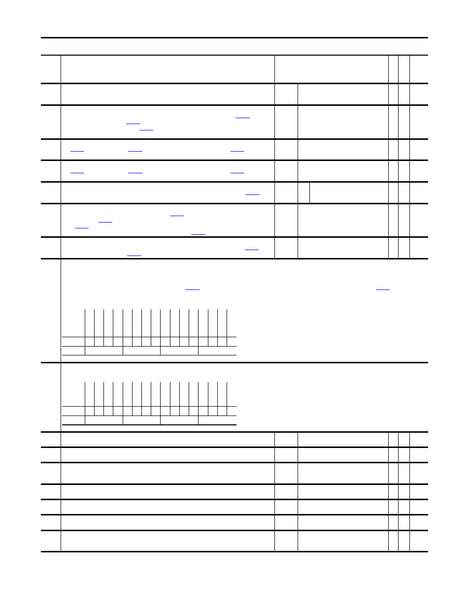
202
Time Axis Rate
Sets rate (1/sec) for the Time Function Generator to ramp from an output of 0 to 1 and from 1 to 0.
Default:
Min/Max:
Units:
1.0000
0.0100/20.0000
/s
Y
RW Real
203
Time Axis Output
The output of the Time Function Generator. When the Time Function Generator is enabled by
[Logic
Command] bit 3 “Time Axis En”, or
[Control Options], bit 24 “Time Axis En”, the value of this parameter
ramps from 0 to 1 at a rate determined by
[Time Axis Rate]. Conversely, when the Time Function Generator
is disabled, the value of this parameter ramps from 1 to 0.
Default:
Min/Max:
0.0000
0.0000/1.0000
RO
Real
204
LimGen Y axis Mx
Sets
[Limit Gen Hi Out] and
[Limit Gen Lo Out] when the absolute value of
[LimGen X axis
In] is greater than or equal to 1.
Default:
Min/Max:
Units:
0.2500
0.0000/8.0000
P.U.
Y
RW Real
205
LimGen Y axis Mn
Sets
[Limit Gen Hi Out] and
[Limit Gen Lo Out] when the absolute value of
[LimGen X axis
In] is equal to 0.
Default:
Min/Max:
Units:
0.0500
0.0000/8.0000
P.U.
Y
RW Real
206
LimGen X axis In
The X axis input to the Limit Generator. Typically this parameter is linked to a speed reference or to
[Time
Axis Output].
Default:
Min/Max:
Y
Y
Y
RW Real
207
Limit Gen Hi Out
Displays the positive output of the Limit Generator. When
[Limit Gen X axis In] is greater than or equal to
1, this value equals
[Limit Gen Y axis Mx]. When Par 206 [Limit Gen X axis In] is equal to 0, this value
equals
[Limit Gen Y axis Mn]. For values of X Axis input between 0 and 1, the value of this parameter is
interpolated from Y axis min. and max. values. Typically it is linked to
[PI Integ HLim].
Default:
Min/Max:
Units:
8.0000
0.0000/8.0000
P.U.
RO
Real
208
Limit Gen Lo Out
Displays the negative output of the Limit Generator. The value of this parameter is the negative of
[Limit
Gen Hi Out]. Typically it is linked to
[PI Integ LLim].
Default:
Min/Max:
Units:
-8.0000
-8.0000/0.0000
P.U.
RO
Real
210
PeakDtct Ctrl In
Sets the configuration of the two peak/level detectors. Peak detection (when “set” and “hold” are off) causes the output to capture the peak min./max.
• Bit 2 “Peak1SelHigh” and bit 6 “Peak2SelHigh” determine if the peak/level detector is positive or negative. If the bit is set the detector detects positive peaks or levels above the preset. If the bit
is not set the detector detects "valleys" or levels below the preset. The output shows the min. or max. peak.
• Bit 0 “Peak 1 Set” bit is used to reset the output to the value in
[PeakDtct1 Preset] (default 0). Bit 4 “Peak 2 Set” bit is used to reset the output to the value in
[PeakDtct2 Preset]
(default 0).
• Bit 1“Peak 1 Hold” is used to hold the output at the present value in Par 214 [PeakDtct1 Preset]. Bit 5 “Peak 2 Hold” is used to hold the output at the present value in Par 218 [PeakDtct2 Preset].
211
PeakDtct Status
Status of peak/level detectors. A peak detector sets its “Change” bit for one scan when it detects a peak. The” Change” bit is off when set or when the “Hold” bit is on.
212
PkDtct1 In DInt
Integer input to the first peak/level detector.
Default:
Min/Max:
0
-/+2147483648
Y
RW 32-bit
Integer
213
PkDtct1 In Real
Floating point input to the first peak/level detector.
Default:
Min/Max:
0.0000
-/+2200000000.0000
Y
RW Real
214
PeakDtct1 Preset
The first detector (in set or hold modes) compares this value to its input for level detection. When the detector
trips (in set mode) it transfers the value of this parameter to its output.
Default:
Min/Max:
0.0000
-/+2200000000.0000
Y
RW Real
215
PeakDetect1 Out
Output from the first peak/level detector.
Default:
Min/Max:
0.0000
-/+2200000000.0000
RO
Real
216
PkDtct2 In DInt
Integer input to second peak/level detector.
Default:
Min/Max:
0
-/+2147483648
Y
RW 32-bit
Integer
217
PkDtct2 In Real
Floating point input to second peak/level detector.
Default:
Min/Max:
0.0000
-/+2200000000.0000
Y
RW Real
218
PeakDtct2 Preset
The second detector (in set or hold modes) compares this value to its input for level detection. When the detector
trips (in set mode) it transfers the value of this parameter to its output.
Default:
Min/Max:
0.0000
-/+2200000000.0000
Y
RW Real
No.
Name
Description
Values
Link
able
Re
ad
-Write
Da
ta
T
yp
e
Options
Re
se
rv
ed
Re
se
rv
ed
Re
se
rv
ed
Re
se
rv
ed
Re
se
rv
ed
Re
se
rv
ed
Re
se
rv
ed
Re
se
rv
ed
Re
se
rv
ed
Pe
ak
2S
el
H
ig
h
Pe
ak
2
H
ol
d
Pe
ak
2
S
et
Re
se
rv
ed
Pe
ak
1S
el
H
ig
h
Pe
ak
1
H
ol
d
Pe
ak
1
S
et
Default
x
x
x
x
x
x
x
x
x
0
0
0
0
0
0
0
Bit
15 14 13 12 11 10 9
8
7
6
5
4
3
2
1
0
0 = False
1 = True
Options
Re
se
rv
ed
Re
se
rv
ed
Re
se
rv
ed
Re
se
rv
ed
Re
se
rv
ed
Re
se
rv
ed
Re
se
rv
ed
Re
se
rv
ed
Re
se
rv
ed
Re
se
rv
ed
Re
se
rv
ed
Re
se
rv
ed
Re
se
rv
ed
Re
se
rv
ed
Pe
ak 2 C
hng
Pe
ak 1 C
hng
Default
x
x
x
x
x
x
x
x
x
x
x
x
x
x
0
0
Bit
15 14 13 12 11 10 9
8
7
6
5
4
3
2
1
0
0 = False
1 = True