Par 902 – Rockwell Automation 20D PowerFlex 700S AC Drives with Phase II Control Programming Manual User Manual
Page 118
118
Rockwell Automation Publication 20D-PM001C-EN-P - July 2013
Chapter 2
Programming and Parameters
No.
Name
Description
Values
Li
nk
ab
le
Re
ad
-W
ri
te
Da
ta
T
ype
902
903
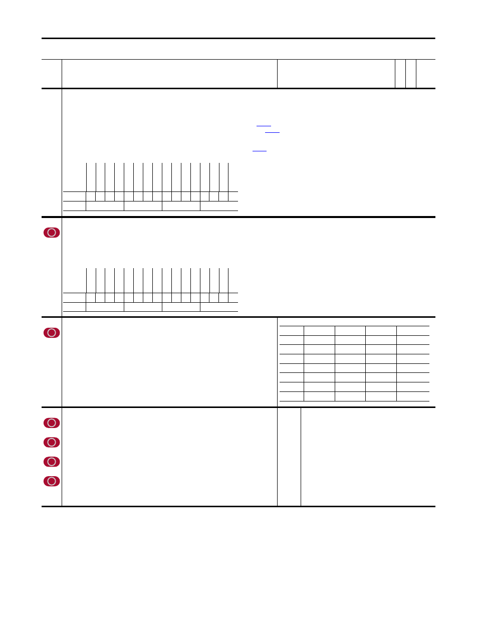
SL Error Status
SL Error History
Indicates the presence of SynchLink faults. This data is visible on the SynchLink diagnostics tab of the Peer Communication window.
• Bit 0 “Sync Loss” indicates SynchLink communication has failed, after it had been established.
• Bit 1 “Rx Loss” indicates the receive port is not receiving data, and the receive port configuration is set to receive data.
• Bit 2 “Many BOF Err” indicates the number of Beginning Of Frame (BOF) errors exceeds limit set by
[SL BOF Err Limit].
• Bit 3 “Many CRC Err” indicates the number of Cyclic Redundancy Check (CRC) errors exceeds limit set by
[SL CRC Err Limit].
• Bit 4 “Pckg Msg Err” indicates the received package sequence number has not matched for 1.0S.
• Bit 5 “CommForm Err” indicates the format of received data does not match the configuration of the receive port.
• Bit 6 “Sys Rev Err” indicates the system revision in the received data does not match the value of
[SynchLink Rev].
• Bit 7 “Mult TKeeper” indicates more than one node on the SynchLink system is configured as a time keeper.
904
SL Node Cnfg
Set bits to configure the SynchLink node.
• Setting bit 0 “Time Keeper” configures the local node as the Time Master.
• Setting bit 2 “Sync Now” configures the node to synchronize with the Time Master immediately (1-2S per node) on power-up or recovery. If you do not set bit 2, the node will stay in the fast
mode, taking up to 36S per node to synchronize on power-up or recovery.
• Setting bit 3 “Reset SL” resets SynchLink. This can be used to reset SynchLink after a configuration change instead of cycling the drive’s power.
Note: This parameter was changed to non-linkable for firmware version 3.001.
905 SL
Rx
CommFormat
Defines the node's communication format for receiving SynchLink data. This determines the number of axis data,
direct data and buffered data words received. Configure the format by using the Peer Communication window in
the DriveExecutive™ programming software.
• Option 14 can be used to allow the drive to receive position data that can be used as a position reference.
Notes: Options 6 and 16 were added for firmware version 2.004. Option 14 was added and this parameter was
changed to non-linkable for firmware version 3.001.
906
907
908
909
SL Rx DirectSel0
Determines the destination for the data received at word 0 of direct received data. Configure
the selection by using the Peer Communication window.
SL Rx DirectSel1
Determines the destination for the data received at word 1 of direct received data. Configure
the selection by using the Peer Communication window.
SL Rx DirectSel2
Determines the destination for the data received at word 2 of direct received data. Configure
the selection by using the Peer Communication window.
SL Rx DirectSel3
Determines the destination for the data received at word 3 of direct received data. Configure
the selection by using the Peer Communication window.
Notes: Options 16 - 26 were added for firmware version 2.004. These parameters were
changed to non-linkable for firmware version 3.001.
Default:
Options:
0 =
0 =
1 =
2 =
3 =
4 =
5 =
6 =
7 =
8 =
9 =
10 =
11 =
12 =
13 =
“No Data”
“No Data”
14 = “Reserved”
“SL Multiply”
15 = “Reserved”
“Event P0”
16 = “Reserved”
“Event P1”
17 = “Reserved”
“Reserved”
18 = “Reserved”
“Reserved”
19 = “Reserved”
“Reserved”
20 = “Reserved”
“Reserved”
21 = “Dir Tx Data”
“Reserved”
22 = “Dir Rx Data”
“Reserved”
23 = “E0 Accum”
“Event Status”
24 = “E1 Accum”
“Reserved”
25 = “Opt0 Accum”
“Reserved”
26 = “Opt1 Accum”
“Reserved”
Options
Re
se
rv
ed
Re
se
rv
ed
Re
se
rv
ed
Re
se
rv
ed
Re
se
rv
ed
Re
se
rv
ed
Re
se
rv
ed
Re
se
rv
ed
Mul
t T
im
eK
pr
Sy
s R
ev
E
rr
Co
mm F
rm
t Er
Pc
kg
M
sg
E
rr
Ma
ny
CR
C Err
Man
y BOF Err
Rx
L
os
s
Sy
nc
L
oss
Default
x
x
x
x
x
x
x
x
0
0
0
0
0
0
0
0
Bit
15 14 13 12 11 10 9
8
7
6
5
4
3
2
1
0
0 = False
1 = True
Options
Re
se
rv
ed
Re
se
rv
ed
Re
se
rv
ed
Re
se
rv
ed
Re
se
rv
ed
Re
se
rv
ed
Re
se
rv
ed
Re
se
rv
ed
Re
se
rv
ed
Re
se
rv
ed
Re
se
rv
ed
Re
se
rv
ed
Re
se
t S
L
Sy
nc
Now
Re
se
rv
ed
Ti
m
e Ke
ep
er
Default
x
x
x
x
x
x
x
x
x
x
x
x
0
0
x
0
Bit
15 14 13 12 11 10 9
8
7
6
5
4
3
2
1
0
0 = False
1 = True
Value
Axis (A)
Direct (D)
Buffered (B)
Options
0
0
0
0
6
1
2
4
7
0
2
18
9
0
4
8
14
1
3
14
16
1
4
4
17
0
4
18