Rockwell Automation 20D PowerFlex 700S AC Drives with Phase II Control Programming Manual User Manual
Page 111
Rockwell Automation Publication 20D-PM001C-EN-P - July 2013
111
Programming and Parameters
Chapter 2
807
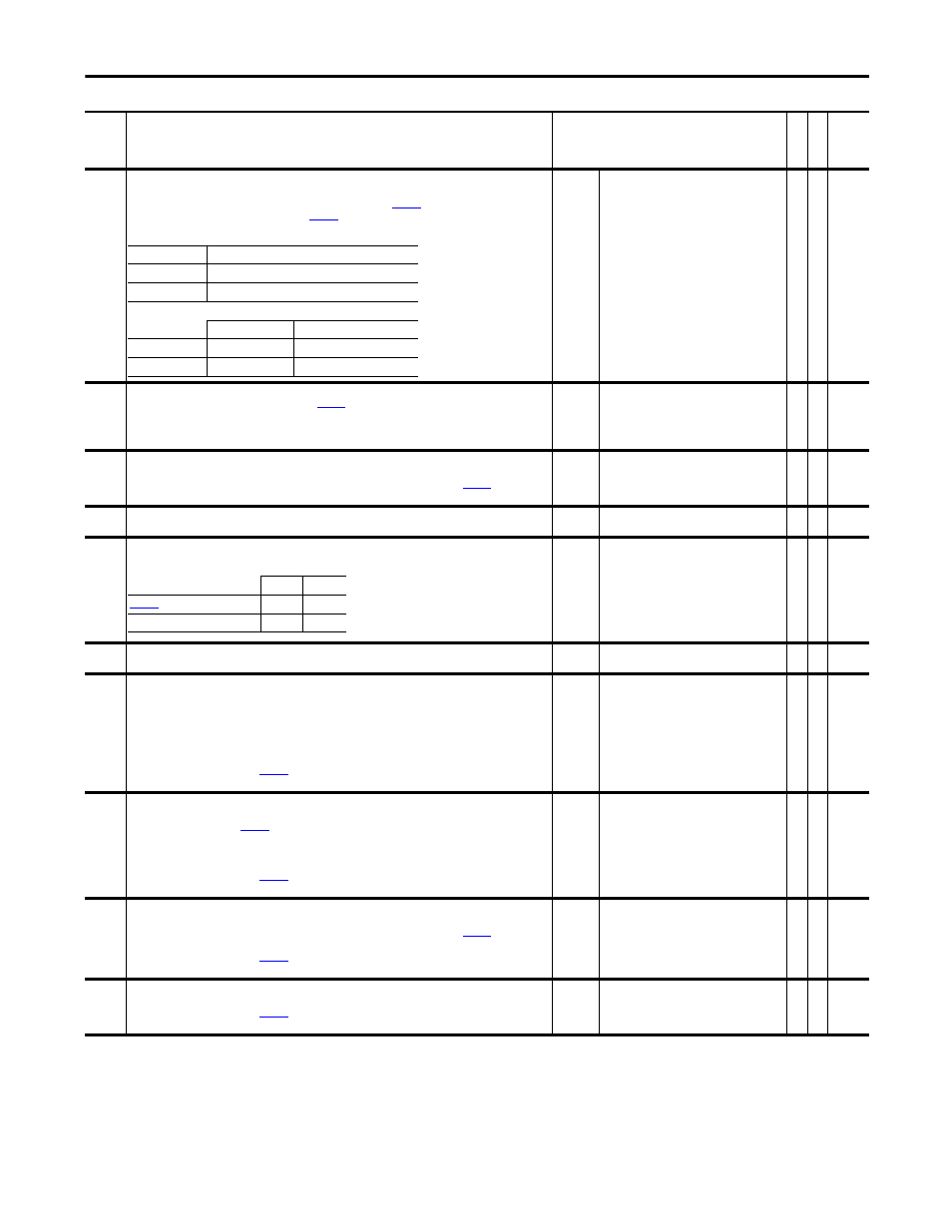
Anlg In2 Value
Displays the actual input value at Analog Input 2. Analog Input 2 may be configured for voltage or current input
signal. For proper selection of the input signal, the DIP switch S-5 and
[Analog I/O Units] must be set to
match. Par 807 [Anlg In2 Value] is multiplied by
[Anlg In2 Scale] produce the input to the lead lag filter
function.
Default:
Min/Max:
Units:
0.0000
-/+20.0000
V/mA
RO Real
808
Anlg In2 Scale
Scales the range of Analog Input 2 to the range of
[Anlg In2 Data]. Enter the units you want per volt or
mA. For example: If Par 807 [Anlg In2 Value] = 0 - 10V and you enter “6” in this parameter, Par 806 [Anlg In2
Data] will equal 0 - 60V.
Par 807 x Par 808 = Par 806.
Default:
Min/Max:
Units:
0.1000
-/+2200000000.0000
/V or /mA
Y
RW Real
809
Anlg In2 Offset
Applies an offset to Analog Input 2. Use the offset to correct for zero signal errors or to create an offset to the
actual input. The output of the A/D converter is summed with this parameter to produce
[Anlg In2
Value].
Default:
Min/Max:
Units:
0.0000
-/+20.0000
V/mA
Y
RW Real
810
AI 2 Filt Gain
Provides the Lead term for the Analog Input 2 filter.
Default:
Min/Max:
1.0000
-/+5.0000
Y
RW Real
811
Anlg In2 Filt BW
Sets the frequency for the Analog Input 2 filter.
Default:
Min/Max:
Units:
0.0000
0.0000/3760.0000
rad/s
Y
RW Real
812
Anlg In3 Data
Displays the scaled final value for Analog Input 3.
Default:
Min/Max:
0.0000
-/+2200000000.0000
RO Real
813
Anlg In3 Value
Displays the actual input value at Analog Input 3. Analog Input 3 is a uni-polar voltage input only and cannot be
configured for current.
Type of Input
= Voltage
Polarity
= Uni-Polar
Resolution
= 10 bit (0 to +1023)
Note: When bit 2 “AI3 Thermstr” of
[Analog I/O Units] is set (= 1), this parameter cannot be viewed from
the HIM.
Default:
Min/Max:
Units:
0.0000
0.0/10.0
V
RO Real
814
Anlg In3 Scale
Scales the raw analog input data plus the input offset (if any) to the desired data range. The scaled data for
Analog Input 3 is displayed in
[Anlg In3 Data] and is available for usage in the drive. Enter the units you
want per volt. For example: If Par 813 [Anlg In3 Value] = 0 - 10V and you enter “6” in this parameter, Par 812
[Anlg In3 Data] will equal 0 - 60V.
Par 813 x Par 814 = Par 812.
Note: When bit 2 “AI3 Thermstr” of
[Analog I/O Units] is set (= 1), this parameter cannot be viewed from
the HIM.
Default:
Min/Max:
Units:
0.1000
-/+2200000000.0000
/V
Y
RW Real
815
Anlg In3 Offset
Applies an offset to Analog Input 3. Use the offset to correct for zero signal errors or to create an offset to the
actual input. The output of the A/D converter is summed with this parameter to produce
[Anlg In3
Value].
Note: When bit 2 “AI3 Thermstr” of
[Analog I/O Units] is set (= 1), this parameter cannot be viewed from
the HIM.
Default:
Min/Max:
Units:
0.0000
-/+20.0
V
Y
RW Real
816
AI 3 Filt Gain
Provides the Lead term for the Analog Input 3 filter.
Note: When bit 2 “AI3 Thermstr” of
[Analog I/O Units] is set (= 1), this parameter cannot be viewed from
the HIM.
Default:
Min/Max:
1.0000
-/+5.0
Y
RW Real
No.
Name
Description
Values
Link
able
Re
ad
-Write
Da
ta
T
yp
e
Type of Input:
Configurable, Voltage or Current
Polarity:
Bi-Polar
Resolution:
14 bit (-8191 to +8191)
DIP Switch
Analog I/O Units
AI 2 Voltage
S5-1 = Open
Par 821 Bit 1 = 0 (False)
AI 2 Current
S5-1 = Closed
Par 821 Bit 1 = 1 (True)
Light
Heavy
[Al 2 Filt Gain
0.25
0.1
Par 811 [Anlg In2 Filt BW]
50
10