Par 728 – Rockwell Automation 20D PowerFlex 700S AC Drives with Phase II Control Programming Manual User Manual
Page 104
104
Rockwell Automation Publication 20D-PM001C-EN-P - July 2013
Chapter 2
Programming and Parameters
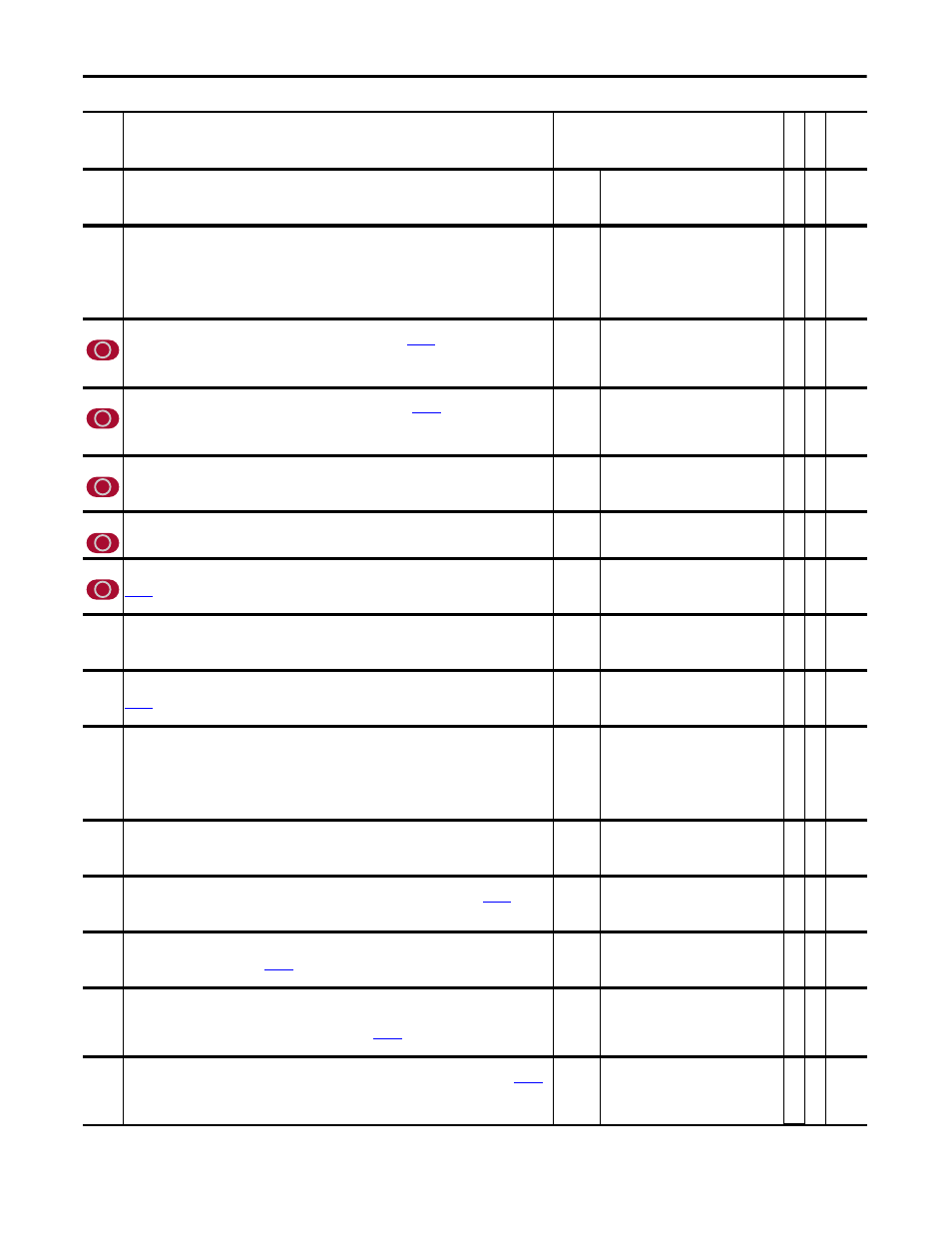
721
PLL Position Ref
Physical encoder position input. This parameter is normally linked directly to the encoder position of the device
chosen for input to PLL.
Note: This parameter was added for firmware version 3.001.
Default:
Min/Max:
0.0
-/+2147483648
Y
RW 32-bit
Integer
722
PLL BandWidth
Sets the internal bandwidth response of the PLL function in (rad/sec). The setting for very noisy mechanical
systems could range from 1 to 10 (rad/s) while well-behaved high line count input devices could range upwards
of 100 (rad/s). Higher bandwidths will quickly resolve tracking errors while the lower bandwidths will take longer
to settle into a steady state. Some adjustment will be necessary to effect the best compromise between noise and
tracking response.
Note: This parameter was added for firmware version 3.001.
Default:
Min/Max:
Units:
20.00
0.00/8000.00
rad/s
Y
RW Real
723
PLL Rev Input
Revolution of the input encoder. This parameter must be coordinated with
[PLL Rev Out] to resolve the
gear-ratio between input revolutions and output (virtual) revolutions. The ratio of input to output revolutions can
always be resolved into integer values and should be reduced to their lowest common factor.
Note: This parameter was added for firmware version 3.001.
Default:
Min/Max:
1
-/+ 1000000
RW 32-bit
Integer
724
PLL Rev Output
Revolution of the output encoder. This parameter must be coordinated with
[PLL Rev In] to resolve the
gear-ratio between input revolutions and output (virtual) revolutions. The ratio of input to output revolutions can
always be resolved into integer values and should be reduced to their lowest common factor.
Note: This parameter was added for firmware version 3.001.
Default:
Min/Max:
1
1/2000000
RW 32-bit
Integer
725
PLL EPR Input
Edges Per Revolution of the physical input device. Use highest line count device possible to insure smoother PLL
operation.
Note: This parameter was added for firmware version 3.001.
Default:
Min/Max:
Units:
1048576
1/67108864
EPR
RW 32-bit
Integer
726
PLL EPR Output
Edges Per Revolution of virtual the physical output device.
Note: This parameter was added for firmware version 3.001.
Default:
Min/Max:
Units:
1048576
1/67108864
EPR
RW 32-bit
Integer
727
PLL VirtEncdrRPM
Revolutions per minute (rpm) of the virtual output device. The value specified determines the 1 P.U. velocity at
[PLL Speed Out] and does not otherwise affect performance.
Note: This parameter was added for firmware version 3.001.
Default:
Min/Max:
Units:
1750.0
1.0/30000.0
rpm
RW Real
728
PLL Ext Spd Ref
External Speed Reference. This is a velocity feed forward input. It is normally linked to an external velocity
reference or the velocity output of the chosen physical encoder.
Note: This parameter was added for firmware version 3.001.
Default:
Min/Max:
Units:
0.0
-/+2200000000.0
P.U.
Y
RW Real
729
PLL Ext SpdScale
External Speed Scale. This parameter is used to properly scale the velocity feed forward. Adjust for zero average at
[PLL FiltPositOut] while running at moderate speed.
Note: This parameter was added for firmware version 3.001.
Default:
Min/Max:
1.0
-/+2200000000.0
Y
RW Real
730
PLL LPFilter BW
Low Pass Filter BandWidth (BW). The filter has two functions:
• Basic noise reduction of input velocity.
• Timed delay of input when feed forward is linked to an external master reference other than an input encoder.
The filter BW should be set for best tracking which occurs when the filter output coincides with the Loop filter
output of PLL. Usually that means setting its BW to the bandwidth of the master reference drive.
Note: This parameter was added for firmware version 3.001.
Default:
Min/Max:
Units:
50.00
0.00/8000.00
rad/s
Y
RW Real
731
PLL Posit Out
Phased Locked Loop position output. This signal is precisely in phase with the input physical device. A link should
be made to it from the local drive auxiliary position input. (The local drive is the one implementing PLL.)
Note: This parameter was added for firmware version 3.001.
Default:
Min/Max:
0
-/+2147483648
RO 32-bit
Integer
732
PLL Posit OutAdv
Phased Locked Loop position advanced output. This signal is one position sample in advance of
[PLL Posit
Out]. A link is normally made to this parameter from SynchLink.
Note: This parameter was added for firmware version 3.001.
Default:
Min/Max:
0
-/+2147483648
RO 32-bit
Integer
733
PLL FiltPositOut
Phased Locked Loop internal low pass filter output. This parameter is normally used to properly scale an external
velocity reference. See description of
[PLL Ext SpdScale].
Note: This parameter was added for firmware version 3.001.
Default:
Min/Max:
Units:
0.0
-/+2200000000.0
P.U.
Y
RW Real
734
PLL Speed Out
Phased Locked Loop velocity output. This signal is used as a velocity feed forward. It is precisely in phase with the
physical input device. A link should be made to it from one of the inputs on the local drive. (The local drive is the
one implementing PLL.) The 1 P.U. rpm of this parameter is set by
[PLL VirtEncdrRPM].
Note: This parameter was added for firmware version 3.001.
Default:
Min/Max:
Units:
0.0
-/+2200000000.0
P.U.
Y
RW Real
735
PLL SpeedOut Adv
Phase Locked Loop velocity advanced output. This signal is one velocity reference sample in advance of
[PLL Speed Out]. A link is normally made to this parameter from SynchLink. (Velocity reference is performed in
the same task as the position regulator.)
Note: This parameter was added for firmware version 3.001.
Default:
Min/Max:
Units:
0.0
-/+2200000000.0
P.U.
Y
RW Real
No.
Name
Description
Values
Link
able
Re
ad
-Write
Da
ta
T
yp
e