Par 1022 – Rockwell Automation 20D PowerFlex 700S AC Drives with Phase II Control Programming Manual User Manual
Page 121
Rockwell Automation Publication 20D-PM001C-EN-P - July 2013
121
Programming and Parameters
Chapter 2
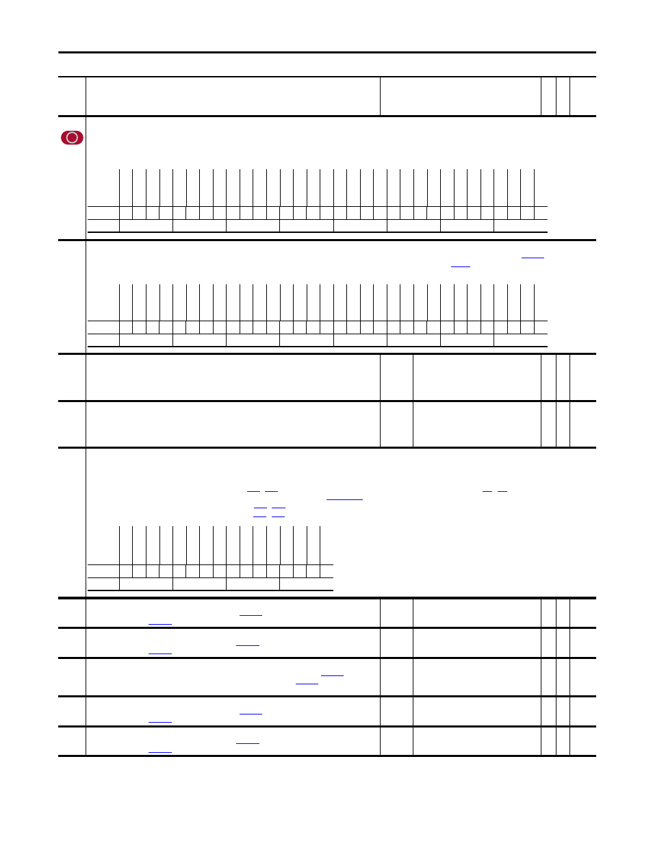
1000
UserFunct Enable
This parameter is used to enable and disable the optional user functions. If a bit is set the corresponding function in enabled. If the bit is not set the corresponding function is disabled and will not
be processed (outputs will not be updated).
Notes: Bit 16 “Ratio Calc” was added for firmware version 2.004. Bit 5 “AddSub Math” and bit 6 “Delay Timer” were added for firmware version 3.001. Bit 7 “EGR” (Electronic Gear Ratio) was added
for firmware version 4.001.
1001
UserFunct Actual
This parameter displays the actual status of the user functions. If a bit is set, then the corresponding function is active. When Par 1001 [UserFunct Actual] does not match
[UserFunct Enable]
it is an indication that the function could not activate because of an error. Typically, the limitation is caused by processor overloading. Adjust
[FW TaskTime Sel] to a slower task cycle (more
time).
1002
to
1011
UserData DInt 01
to
UserData DInt 10
These are general purpose parameters available for storage of 32-bit enumerated data or DInt data by the user.
These parameters will be retained through power cycles.
Default:
Min/Max:
0
-/+2147483648
Y
RW 32-bit
Integer
1012
to
1021
User Data Real 01
to
UserData Real 10
These are general purpose parameters available for storage of Real data by the user. These parameters will be
retained through power cycles.
Default:
Min/Max:
0.0000
-/+2200000000.0000
Y
RW Real
1022
Sel Switch Ctrl
This is the control parameter for the switches used by the Selector Switch user functions. 16 Input Selector Switches (Pars 1029 - 1044) are controlled by bits 1-4.
• Bit 0 “SSW DataPass” Updates the output. If bit 0 is low, the output is NOT updated with the selected input.
• Bits 1 “Sel Swtch 00” - 4 “Sel Swtch 03” Binary coded selection of the 16 inputs to the switch. Bit 1 is the Least Significant Bit. If these bits are all low (set to “0”), Par 1029 is selected. If these bits
are all high (set to “1”) Par 1044 is selected. (Refer to Pars
.) The values in these bits can be controlled by the digital inputs. (Refer to Pars
-
and to the “Selector Switches”
section of the PowerFlex 700S Drives with Phase II Control - Reference Manual, publica
, for more information.)
• Bit 5 “SW Real 1 On” activates the Real switch. (Refer to Pars
• Bit 6 “SW DInt 1 On” activates the DInt switch. (Refer to Pars
-
1023
Swtch Real 1 NC
This is the Normally Closed input to the Real switch. When
[Sel Switch Ctrl], bit 5 “SW Real 1 On” is low,
this input is updated to
[Swtch Real 1 Output].
Default:
Min/Max:
0.0000
-/+2200000000.0000
Y
RW Real
1024
Swtch Real 1 NO
This is the Normally Open input to the Real switch. When
[Sel Switch Ctrl], bit 5 “SW Real 1 On” is high,
this input is updated to
[Swtch Real 1 Output].
Default:
Min/Max:
0.0000
-/+2200000000.0000
Y
RW Real
1025
Swtch Real 1 Out
This is the result of the Real switch. The output is loaded with the selected input based on
[Sel Switch
Ctrl], bit 5 “SW Real 1 On”. If this parameter does not update, check the setting of
[UserFunct Enable], bit
1 “User Params”.
Default:
Min/Max:
0.0000
-/+2200000000.0000
RO Real
1026
Swtch DInt 1 NC
This is the Normally Closed input to the DInt switch. When
[Sel Switch Ctrl], bit 6 “SW DInt 1 On” is low,
this input is updated to
[Swtch DInt 1 Output].
Default:
Min/Max:
0.0000
-/+2200000000.0000
Y
RW 32-bit
Integer
1027
Swtch DInt 1 NO
This is the Normally Open input to the Real switch. When
[Sel Switch Ctrl], bit 6 “SW DInt 1 On” is high,
this input is updated to
[Swtch DInt 1 Output].
Default:
Min/Max:
0.0000
-/+2200000000.0000
Y
RW 32-bit
Integer
No.
Name
Description
Values
Link
able
Re
ad
-Write
Da
ta
T
yp
e
Options
Re
se
rv
ed
Re
se
rv
ed
Re
se
rv
ed
Re
se
rv
ed
Re
se
rv
ed
Re
se
rv
ed
Re
se
rv
ed
Re
se
rv
ed
Re
se
rv
ed
Re
se
rv
ed
Re
se
rv
ed
Re
se
rv
ed
Re
se
rv
ed
Re
se
rv
ed
MOP
Ra
tio C
al
c
Re
se
rv
ed
Re
se
rv
ed
Re
se
rv
ed
Re
se
rv
ed
Re
se
rv
ed
Re
se
rv
ed
Re
se
rv
ed
Re
se
rv
ed
EGR
Del
ay
T
ime
r
Ad
dS
ub
M
at
h
Mul
D
iv Ma
th
Lo
gi
c Fu
nc
ts
Co
nv
er
ts
Se
l S
wi
tc
hes
Us
er
P
ar
am
s
Default
x
x
x
x
x
x
x
x
x
x
x
x
x
x
1
0
x
x
x
x
x
x
x
x
0
1
1
1
1
1
1
1
Bit
31 30 29 28 27 26 25 24 23 22 21 20 19 18 17 16 15 14 13 12 11 10 9
8
7
6
5
4
3
2
1
0
0 = False
1 = True
Options
Re
se
rv
ed
Re
se
rv
ed
Re
se
rv
ed
Re
se
rv
ed
Re
se
rv
ed
Re
se
rv
ed
Re
se
rv
ed
Re
se
rv
ed
Re
se
rv
ed
Re
se
rv
ed
Re
se
rv
ed
Re
se
rv
ed
Re
se
rv
ed
Re
se
rv
ed
MOP
Re
se
rv
ed
Re
se
rv
ed
Re
se
rv
ed
Re
se
rv
ed
Re
se
rv
ed
Re
se
rv
ed
Re
se
rv
ed
Re
se
rv
ed
Re
se
rv
ed
Re
se
rv
ed
Re
se
rv
ed
Re
se
rv
ed
Mul
D
iv
Ma
th
Lo
gi
c Fu
nc
ts
Co
nv
er
ts
Sel
S
w
itc
he
s
Use
r P
ara
ms
Default
x
x
x
x
x
x
x
x
x
x
x
x
x
x
0
x
x
x
x
x
x
x
x
x
x
x
x
0
0
0
0
0
Bit
31 30 29 28 27 26 25 24 23 22 21 20 19 18 17 16 15 14 13 12 11 10 9
8
7
6
5
4
3
2
1
0
0 = False
1 = True
Options
Re
se
rv
ed
Re
se
rv
ed
Re
se
rv
ed
Re
se
rv
ed
Re
se
rv
ed
Re
se
rv
ed
Re
se
rv
ed
Re
se
rv
ed
Re
se
rv
ed
SW
D
In
t 1 On
SW
R
eal
1 On
Sel
S
w
tch
03
Sel
S
w
tch
02
Sel
S
w
tch
01
Sel
S
w
tch
00
SS
W
D
at
aP
ass
Default
x
x
x
x
x
x
x
x
x
0
0
0
0
0
0
0
Bit
15 14 13 12 11 10 9
8
7
6
5
4
3
2
1
0
0 = False
1 = True