5 and, Par 821 – Rockwell Automation 20D PowerFlex 700S AC Drives with Phase II Control Programming Manual User Manual
Page 112
112
Rockwell Automation Publication 20D-PM001C-EN-P - July 2013
Chapter 2
Programming and Parameters
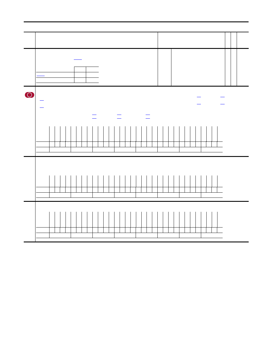
817
Anlg In3 Filt BW
Provides the Lag term for the Analog Input 3 filter.
Note: When bit 2 “AI3 Thermstr” of
[Analog I/O Units] is set (= 1), this parameter cannot be viewed from
the HIM.
Default:
Min/Max:
Units:
0.0000
0.0000/3760.0000
rad/s
Y
RW Real
821
Analog I/O Units
Use to configure the type of units (voltage or current) for the analog I/O.
• For analog input 1, configure bit 0 to match the selection of hardware switch S5-2; bit 0 set to “0” = V, or set to “1” = mA. Also, the units for Pars
[Anlg In1 Scale], and
[Anlg In1 Offset] will correspond to this setting.
• For analog input 2, configure bit 1 to match the selection of hardware switch S5-1; bit 1 set to “0” = V, or set to “1” = mA. Also, the units for Pars
[Anlg In2 Scale], and
[Anlg In2 Offset] will correspond to this setting.
• Bit 2 “AI3 Thermstr” configures analog input 3 for a thermistor input with range of 0 to 10V.
• For analog output 1, use bit 16 to configure Pars
[Anlg Out1 Scale],
[Anlg Out1 Zero], and
[Anlg Out1 Value] for voltage or current; bit 16 set to “0” = V, or set to “1” = mA.
• For analog output 2, use bit 17 to configure Pars
[Anlg Out2 Scale],
[Anlg Out2 Zero], and
[Anlg Out2 Value] for voltage or current; bit 16 set to “0” = V, or set to “1” = mA.
No hardware configuration is needed for the analog outputs.
823
DigIn Debounce
Sets the amount of de-bounce (filtering) for each digital input. This is used to remove unwanted on/off cycling (chatter) on the digital inputs caused by relay bounce. Each digital input de-bounce is
configured separately from 0.5ms to 8.0ms. The bit selections are cumulative for each digital input (1 - 6).
Example: bit 4 & 2 & 1 on = 5.5ms of de-bounce for digital input 1.
824
Local I/O Status
Displays the status of the local I/O.
No.
Name
Description
Values
Link
able
Re
ad
-Write
Da
ta
T
yp
e
Light
Heavy
[Al 3 Filt Gain
0.25
0.1
Par 817 [Anlg In3 Filt BW]
50
10
Options
Re
se
rv
ed
Re
se
rv
ed
Re
se
rv
ed
Re
se
rv
ed
Re
se
rv
ed
Re
se
rv
ed
Re
se
rv
ed
Re
se
rv
ed
Re
se
rv
ed
Re
se
rv
ed
Re
se
rv
ed
Re
se
rv
ed
Re
se
rv
ed
Re
se
rv
ed
AO
2 Cu
rr
en
t
AO
1 Cu
rr
en
t
Re
se
rv
ed
Re
se
rv
ed
Re
se
rv
ed
Re
se
rv
ed
Re
se
rv
ed
Re
se
rv
ed
Re
se
rv
ed
Re
se
rv
ed
Re
se
rv
ed
Re
se
rv
ed
Re
se
rv
ed
Re
se
rv
ed
Re
se
rv
ed
AI3 T
her
mstr
AI2 C
urr
en
t
AI1 C
urr
en
t
Default
x
x
x
x
x
x
x
x
x
x
x
x
x
x
0
0
x
x
x
x
x
x
x
x
x
x
x
x
x
0
0
0
Bit
31 30 29 28 27 26 25 24 23 22 21 20 19 18 17 16 15 14 13 12 11 10 9
8
7
6
5
4
3
2
1
0
0 = False
1 = True
Options
Re
se
rv
ed
DI
6 8.0m
s
DI
6 4.0m
s
DI
6 2.0m
s
DI
6 1.0m
s
DI
6 0.5m
s
DI
5 8.0m
s
DI
5 4.0m
s
DI
5 2.0m
s
DI
5 1.0m
s
DI
5 0.5m
s
DI
4 8.0m
s
DI
4 4.0m
s
DI
4 2.0m
s
DI
4 1.0m
s
DI
4 0.5m
s
DI
3 8.0m
s
DI
3 4.0m
s
DI
3 2.0m
s
DI
3 1.0m
s
DI
3 0.5m
s
DI
2 8.0m
s
DI
2 4.0m
s
DI
2 2.0m
s
DI
2 1.0m
s
DI
2 0.5m
s
DI
1 8.0m
s
DI
1 4.0m
s
DI
1 2.0m
s
DI
1 1.0m
s
DI
1 0.5m
s
Re
se
rv
ed
Default
x
0
0
0
0
0
0
0
0
0
0
0
1
0
1
0
0
0
0
0
0
0
0
1
0
0
0
0
0
0
1
x
Bit
31 30 29 28 27 26 25 24 23 22 21 20 19 18 17 16 15 14 13 12 11 10 9
8
7
6
5
4
3
2
1
0
0 = False
1 = True
Options
Res
er
ve
d
Res
er
ve
d
Res
er
ve
d
Res
er
ve
d
Res
er
ve
d
Res
er
ve
d
Res
er
ve
d
Res
er
ve
d
Res
er
ve
d
Res
er
ve
d
Res
er
ve
d
Res
er
ve
d
Res
er
ve
d
Rel
ay O
ut 3
Di
gO
ut
2
Di
gO
ut
1
Sa
feOff
In
put
Res
er
ve
d
Res
er
ve
d
Res
er
ve
d
Res
er
ve
d
Res
er
ve
d
Res
er
ve
d
Res
er
ve
d
Res
er
ve
d
Di
gI
n 6
Di
gI
n 5
Di
gI
n 4
Di
gI
n 3
Di
gI
n 2
Di
gI
n 1
Hw Enbl Byps
Default
x
x
x
x
x
x
x
x
x
x
x
x
0
0
0
0
x
x
x
x
x
x
x
x
0
0
0
0
0
0
0
Bit
31 30 29 28 27 26 25 24 23 22 21 20 19 18 17 16 15 14 13 12 11 10 9
8
7
6
5
4
3
2
1
0
0 = False
1 = True