Rockwell Automation 20D PowerFlex 700S AC Drives with Phase II Control Programming Manual User Manual
Page 44
44
Rockwell Automation Publication 20D-PM001C-EN-P - July 2013
Chapter 2
Programming and Parameters
154
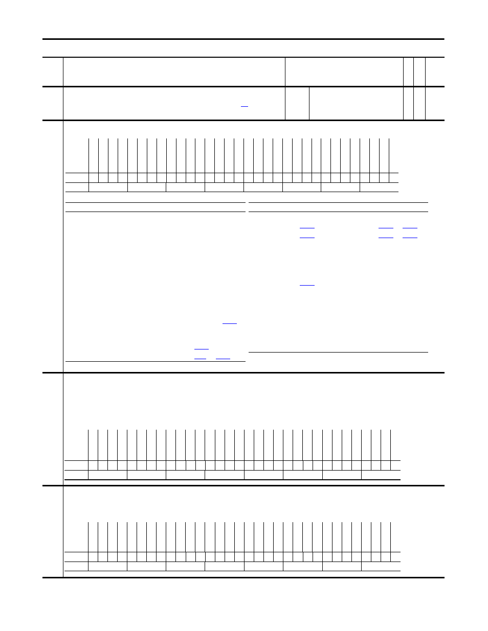
Stop Dwell Time
Sets an adjustable delay time between detecting zero speed and disabling the speed and torque regulators, when
responding to a stop command. For more information, please see Stop Dwell Time on page
Important:
Consult industry and local codes when setting the value of this parameter.
Default:
Min/Max:
Units:
0.0000
0.0000/10.0000
s
Y
RW Real
155 Logic
Status
Displays the status - condition of the drive.
156
Start Inhibits
Indicates which condition is preventing the drive from starting or running.
• Bit 16 “GateShutDown” is set when the shunt jumper in the 16-15 position on the Main Control board is missing and a Safe-Off option board is not present.
• Bit 17 “SafeOff Enbl” is set when the HW Enable jumper (P22) is in the Bypass position (on pins 1&3) and the Safe-Off option board is present. A HW Enable is required when a safe-off board is
used.
• Bit 21 “Sleep Stop” is set when the sleep mode has stopped the drive.
• Bit 22 “Sleep Config” is set when sleep mode has not been setup correctly. Check the sleep/wake levels and digital input configuration.
Note: Bit 18 “MC Config” was added to this parameter for firmware version 2.003. Added bit 20 “High BusVolt” for firmware version 4.001. Bits 21 and 22 were added for firmware version 5.002.
157
Logic Ctrl State
Indicates which logic control functions are enabled.
• Bit 22 “S Tst FulSpd” set to “1” indicates that the Slip Auto Tune function is active
• Bit 23 “Slip Test En” set to “1” indicates that the drive is at speed for the Auto Tune function.
Notes: Bits 22 and 23 were added for firmware version 3.001. Bit 14 “DC Brake En” is not functional.
No.
Name
Description
Values
Link
able
Re
ad
-Write
Da
ta
T
yp
e
Options
Lo
gi
xP
re
se
nt
Spd
Ref
A
ct2
Spd
Ref
A
ct1
Spd
Ref
A
ct0
Re
ser
ve
d
RunC
om
manded
St
ar
t A
ctiv
e
Po
si
tio
nM
od
e
Spe
ed Mode
To
rq
ue
M
od
e
Hw En
abl
e O
n
Spd
C
ommis
M
C C
ommi
s
MC
Ac
tiv
e
Abov
e S
etpt2
At S
etp
t 1
En
ab
le
O
n
At S
etp
t S
pd
At
Z
ero
S
pd
Ta
ch
L
os
s S
w
At
L
im
it
Re
ady
Fl
as
h M
od
e
Al
ar
m
Fa
ul
te
d
Jogging
De
ce
le
ra
tin
g
Ac
ce
le
ra
tin
g
Ac
tu
al
D
ir
Co
m
m
an
d D
ir
Running
Ac
tiv
e
Default
0
0
0
0
0
0
0
0
0
0
0
0
0
0
0
0
0
0
0
0
0
0
0
0
0
0
0
0
0
0
0
0
Bit
31 30 29 28 27 26 25 24 23 22 21 20 19 18 17 16 15 14 13 12 11 10 9
8
7
6
5
4
3
2
1
0
Bit Name
Current Function
Bit
Name
Current Function
0
Active
Drive is controlling motor
15
Enable On
1
Running
Run command received & controlling motor
16
At Setpt 1
value is within limits defined by
2
Command Dir
Commanded direction is forward
17
Above Setpt 2
value is within limits defined by
3
Actual Dir
Actual motor direction is forward
18
MC Active
Drive is controlling motor (same as enabled)
4
Accelerating
Motor is increasing speed
19
MC Commis
Motor control commissioning in progress
5
Decelerating
Motor is decreasing speed
20
Spd Commis
Speed control commissioning in progress
6
Jogging
Jog command received & controlling motor
21
Hw Enable On
7
Faulted
Exception event that causes a fault has occurred
22
Torque Mode
value is 2, 3, 4, 5 or 6
8
Alarm
Exception event that causes an alarm has occurred
23
Speed Mode
Par 110 value is 1 & position control is not enabled
9
Flash Mode
Flash upgrade in progress
24
Position Mode
Position control active & Par 110 value is not 2, 3, 4, 5 or 6
10 Ready
Enable input is high & drive is fault free
25
Start Active
Start command received & controlling motor
11 At Limit
Speed, Power, Current or Torque is being limited, refer to
26
Command Run
Run command received
12 Tach Loss SW
Failure is detected in primary speed or position feedback device &
drive has switched to secondary device
28-30 Spd Ref Act1-3
13 At Zero Spd
Speed feedback is within limits defined in
31
LogixPresent
14 At Setpt Spd
Speed feedback is within limits defined in
and
0 = False
1 = True
Options
Re
se
rv
ed
Re
se
rv
ed
Re
se
rv
ed
Re
se
rv
ed
Re
se
rv
ed
Re
se
rv
ed
Re
se
rv
ed
Re
se
rv
ed
Re
se
rv
ed
Slee
p C
onfig
Slee
p S
top
Hi
gh B
usV
olt
Re
se
rv
ed
MC C
onfig
Saf
eO
ff E
nb
l
Ga
te
Sh
ut
Do
wn
Po
si
tF
db
kS
el
PM Mtr F
db
k
Motin Sh
td
wn
D
igIn C
onfig
Bus P
reC
hr
g
Enc
od
er PPR
Jo
g
Star
t
Fla
sh
U
pg
rd
Po
w
er
E
E
Po
w
er
L
os
s
SW
I Lim S
tp
SW
C
oast
Stp
SW
R
amp
St
op
No E
nable
Fa
ul
te
d
Default
x
x
x
x
x
x
x
x
x
0
0
0
x
0
0
0
0
0
0
0
0
0
0
0
0
0
0
0
0
0
0
0
Bit
31 30 29 28 27 26 25 24 23 22 21 20 19 18 17 16 15 14 13 12 11 10 9
8
7
6
5
4
3
2
1
0
0 = False
1 = True
Options
Pr
ocs
Tr
im E
n
Cm
d D
ir U
po
l
Lg
x I
/O
Cn
x
Lg
x R
un
M
od
e
Re
se
rv
ed
VP
G
at
e
En
bl
MC G
at
e Enbl
Ra
m
p H
ol
d
Slip
T
est
En
S T
st F
ulS
pd
PM O
ff
set Rq
Mtr D
ir Re
q
Pwr
Di
ag
Re
q
MC A
tune Req
FTD
Ramp EN
MC E
n Req
RT
hr
u F
lux
DC
Br
ak
e E
n
Mtr Si
m M
ode
RTh
ru
Co
as
t
Cu
rrRe
f En
Fo
rc
ed
S
pd
Tr
q R
ef
E
n
Spd Reg En
SReg In
tg
Hld
Cu
rL
im
St
op
J T
st
F
ulS
pd
Iner
t T
st En
Po
si
tio
nE
nb
l
SRef
SCr
v E
n
SRef
Ramp En
Spd Ref En
Default
0
0
0
0
x
0
0
0
0
0
0
0
0
0
0
0
0
0
0
0
0
0
0
0
0
0
0
0
0
0
0
0
Bit
31 30 29 28 27 26 25 24 23 22 21 20 19 18 17 16 15 14 13 12 11 10 9
8
7
6
5
4
3
2
1
0
0 = False
1 = True