Par 740 – Rockwell Automation 20D PowerFlex 700S AC Drives with Phase II Control Programming Manual User Manual
Page 105
Rockwell Automation Publication 20D-PM001C-EN-P - July 2013
105
Programming and Parameters
Chapter 2
737
Posit TP Select
Enter or write a value to select position regulator data displayed in
[PositTP DataInt] and
[PositTP
DataReal].
Default:
Options:
0 =
0 =
1 =
2 =
3 =
4 =
5 =
6 =
7 =
8 =
“Zero”
“Zero”
9 = “Limiter Out”
“del Xos Vout”
10 = “Ref EGR In”
“del Xcmd”
11 = “OffsetSpdLim”
“del Act Load”
12 = “Pt-Pt SpdLim”
“del Act Mtr”
13 = “Sec per Edge”
“Integ Error”
14 = “Edge per Sec”
“Xprop Out”
15 = “Ratio Guess”
“Fdbk Sel Alt”
16 = “Sync Count”
“PreLim Xvout”
738
PositTP DataDInt
Displays the integer data selected by
[Posit TP Select]. This display should only be used if the selected
value is Integer data.
Default:
Min/Max:
0
-/+2147483648
RO 32-bit
Integer
739
PositTP DataReal
Displays the real data selected by
[Posit TP Select]. This display should only be used if the selected value is
Real data.
Default:
Min/Max:
0.0
-/+8.0 P.U.
RO Real
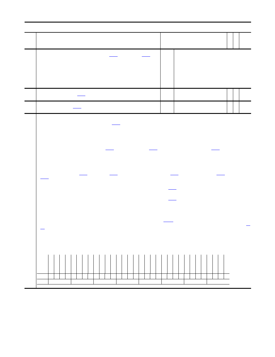
740
Position Control
Set bits to enable various position control functions.
• Setting bit 1 “Speed Out En” enables position regulator output at
[Posit Spd Output].
• Setting bit 2 “Integ En” enables integrator operation. Resetting it resets the integrator.
• Setting bit 3 “Integ Hold” holds integrator in present state.
• Setting bit 4 “X Offset Pol” reverses polarity of offset parameters.
• Setting bit 5 “XOffset Ref” permits changing the value of position offsets without changing actual position. Resetting it makes the position offset relative to the re-referenced value or the
latched value upon enable if re-reference was not performed.
• Bit 6 “AbsPositCtrl” may be set when a multi-turn, absolute feedback device is used for Point-to-Point positioning. Activating this bit will ReRef the position reference to the absolute feedback
when position control is activated in bit 7 “Regulator On” of
[Position Status]. If the value at
[Pt-Pt Posit Ref] is different than the feedback in
error will exist and the machine will move to position when activated. When bit 6 “AbsPositCtrl” is high, bit 9 “SetZeroPosit” of Par 740 [Position Control] may be used to set the zero “home”
position accumulators. This can only be used when the drive is not in run and Par 740 [Position Control] bit 6 = 1 (true).
• Setting bit 7 “AbsoluteMode” puts the position regulator in Absolute mode. When using the Homing function while in Absolute mode, the value in Par 758 [Pt-Pt Posit Ref] must be set relative
to the value in Par 763 [Position Actual] after homing is complete. For example: When homing is complete Par 763 [Position Actual] = 1000 counts. If you want to move to an absolute position
of 2000 counts relative to the home switch, you must enter a value of 3000 counts into Par 758 [Pt-Pt Posit Ref] (i.e., 1000 + 2000 = 3000). If you want to move back to the home switch, using
the same value in Par 763 [Position Actual] after homing (1000), you must enter a value of 1000 into Par 758 [Pt-Pt Position Ref] (i.e., 0 + 1000 = 1000).
• Setting bit 8 “Xzero Preset” presets
[PositRef EGR Out],
[Position Cmmd], Par 763 [Position Actual] and
[Posit Actl Load] with the value in
[Position Fdbk] minus
[Abs Posit Offset] upon drive enable.
• Setting bit 10 “Pt-Pt ReRef” enables setting or changing Par 758 [Pt-Pt Posit Ref] without changing the actual position.
• Setting bit 16 “X Watch1 En” enables position Watch 1. Resetting it clears Par 741 [Position Status] bit 8 “Posit Watch1”.
• Setting bit 17 “X Watch1 Dir” causes Position Watch 1 output to be set when Par 763 [Position Actual] is greater than
[PositDtct1 Stpt]. Re-setting bit 17 causes Position Watch 1 output
to be set when Par 763 [Position Actual] is less than Par 780 [PositDtct1 Stpt].
• Setting bit 18 “X Watch2 En” enables position Watch 2. Resetting it clears Par 741 [Position Status] bit 9 “Posit Watch2”.
• Setting bit 19 “X Watch2 Dir” causes Position Watch 2 output to be set when Par 763 [Position Actual] is greater than
[PositDtct2 Stpt]. Re-setting bit 19 causes Position Watch 2 output
to be set when Par 763 [Position Actual] is less than Par 781 [PositDtct2 Stpt].
• Setting bit 20 “Pt-Pt RampStop” enables the Ramp to Stop function for point-to-point positioning. When reset and the stop command is given during a move, the drive will stop at 0 ramp time.
When set and the stop command is given during a move, the rive will ramp to zero at Par 760 [Pt-Pt Decel Time]. Note: Coast Stop or Removing Enable always causes a Coast to Stop function.
• Bit 24 “Find Home” - when this bit is on and the drive is started, a homing sequence is initiated.
• Bit 25 “Pos Redefine” - when this bit is set the position will be set to zero.
• Bit 26 “Home Dir” - when this bit is set the homing direction will be opposite of the Home Speed commanded in
[Home Speed].
• Bit 27 “Return Home” - when this bit is set the homing direction will be opposite of the Home Speed commanded in P1122 [Home Speed]. Note: The position reference will not change, but
[Posit Load Fdbk] will return to zero. The Position reference should also be redefined to zero to synchronize the position with the command. This can be useful for returning to Home after a
jog type operation
• Bit 28 “Home Switch” - when this bit is set the Homing sequence will look for the home switch to make a transition from it's current state when the homing sequence is started. Do not set with
bit 29 "Home Marker".
• Bit 29 “Home Marker” - when set, the Homing Sequence will look for the Marker pulse. When the marker pulse is found the drive will decelerate and return to the position where the marker was
found. Do not set with bit 28 "Home Switch".
Note: Bits 24 - 29 were added for future use - not active for use with firmware version 3.001 and above.
No.
Name
Description
Values
Link
able
Re
ad
-Write
Da
ta
T
yp
e
Options
Re
se
rv
ed
Re
se
rv
ed
Hom
e M
ark
er
Hom
e Swi
tch
Re
turn Home
Hom
e D
ir
Po
s R
ed
ef
in
e
Fi
nd
H
om
e
Re
se
rv
ed
Re
se
rv
ed
Re
se
rv
ed
Pt
-P
t Ram
pS
to
p
X W
at
ch2
D
ir
X W
at
ch2
E
n
X W
at
ch1
D
ir
X W
at
ch1
E
n
Bs
cI
nd
xStpRv
Bs
cI
nd
x P
rs
t
Bs
cI
nd
x Re
v
Bs
cI
nd
x S
te
p
Bs
cI
nd
x Enb
l
Pt
-P
t Re
Re
f
Se
tZ
er
oP
osit
Xz
er
o P
res
et
Ab
so
lu
te
M
od
e
Ab
sP
os
itC
tr
l
XO
ff
Re
Re
f
X O
ffs
et P
ol
Inte
g Hol
d
Inte
g En
Spe
ed O
ut E
n
Re
se
rv
ed
Default
x
x
0
0
0
0
0
0
x
x
x
0
1
0
1
0
0
0
0
0
0
0
0
1
0
0
0
0
0
0
1
x
Bit
31 30 29 28 27 26 25 24 23 22 21 20 19 18 17 16 15 14 13 12 11 10 9
8
7
6
5
4
3
2
1
0
0 = False
1 = True