Figure 9, For mor – Rockwell Automation 20D PowerFlex 700S AC Drives with Phase II Control Programming Manual User Manual
Page 172
172
Rockwell Automation Publication 20D-PM001C-EN-P - July 2013
Appendix B
Application Notes
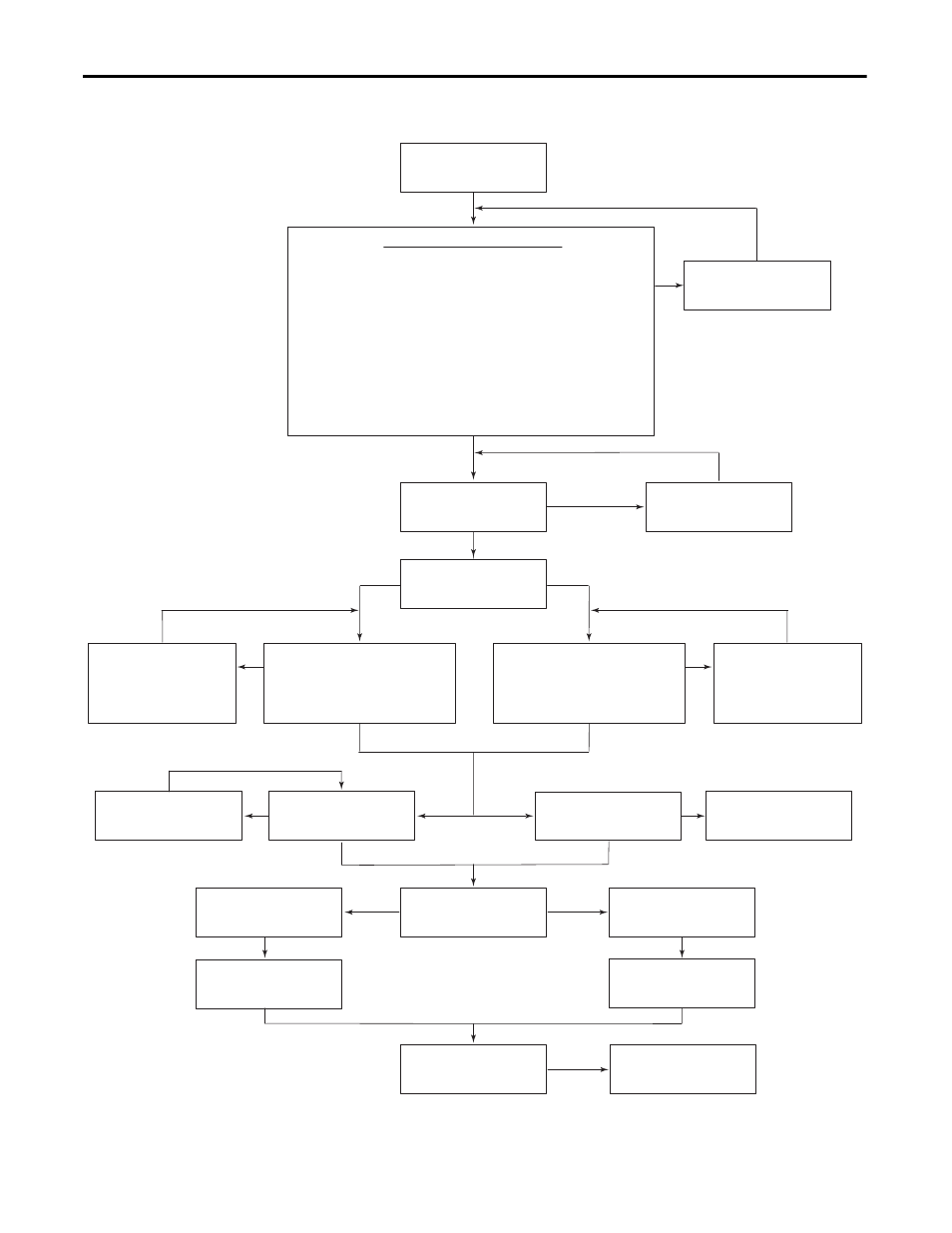
Figure 9 - Sleep-Wake Mode Flow Chart
Is Sleep-Wake
Working?
Have these conditions been met?
Is Required Input Closed?
(Stop, Enable, Run)
Did a Drive
Fault Occur?
Which Required Input
was Chosen?
Meet all Conditions!
Close Input
Reset Fault
Yes
Yes
Stop or Enable
Run
Yes
Yes
Drive Running?
No
Direct
Invert
No
No
No
No
No
No
Issue a Start Command
(HIM, Network or TB)
Open & Close Input
Consult Factory
No
Consult Factory
Which Mode is Selected?
"Invert" or "Direct"
1. [Sleep-Wake Ref] must be set to the analog input that will control
"Start/Stop" functions.
2. [Sleep-Wake Mode] must = "1, Direct" (Enable) or "2, Invert (Enable)."
3. [Sleep Level] must be less than [Wake Level] in Direct mode (or
greater than [Wake Level] in "Invert" mode).
4. [Speed Ref x Sel] must be set to a speed reference source that will
control the drive. If [Sleep-Wake Ref] = [Speed Ref x Sel], the same
analog signal will control start/stop and speed reference.
5. At
least one of the following must be programmed for [Dig Inx Sel]:
"Normal Stop," "Enable," "Start," "Run."
Is Analog Signal
Greater
than or equal to [Wake Level]?
and for time period greater than
or equal to [Wake Time]
Yes
Yes
Is Analog Signal
Less
than or equal to [Wake Level]?
and for time period greater than
or equal to [Wake Time]
Increase Analog Input
Signal and wait for a time
period greater than or
equal to [Wake Time].
Decrease Analog Input
Signal and wait for a time
period greater than or
equal to [Wake Time].
Was a Stop Issued?
or
Power Cycled?