Par 343, N in, Par 344 – Rockwell Automation 20D PowerFlex 700S AC Drives with Phase II Control Programming Manual User Manual
Page 70
70
Rockwell Automation Publication 20D-PM001C-EN-P - July 2013
Chapter 2
Programming and Parameters
343 OL
OpnLp
CurrLim
Displays the current limit set by the Open Loop Inverter Overload (OL) function. This function sets this current limit
based on stator current feedback and the current ratings of the drive - continuous and short term (three-second
rating). Typically the drive will have a sixty-second rating of 110% of continuous current and a three-second
rating at 150% of the continuous. Under normal operating conditions, the open loop function sets this current
limit to the short term (three-second) rating. If the function detects an overload, it lowers the limit to the
continuous level. After a period of time (typically one to three minutes), the function returns the limit to the short
term rating.
Default:
Min/Max:
Units:
8.0000
0.0000/8.0000
P.U.
RO
Real
344
OL ClsLp CurrLim
Displays the current limit set by the Closed Loop Inverter Overload (OL) function. This function will set a current
limit level based on the values in
[Heatsink Temp] and the thermal characteristics
of the drive. Under normal operating conditions, the function typically sets the limit at 250% of the continuous
drive rating. If the function determines that the power device junction temperature is approaching maximum, it
will reduce this limit to the level required to prevent additional heating of the inverter. This level could be as low
as the continuous rating of the drive. If the inverter temperature decreases, the function will raise the limit to a
higher level. Disable this protection by setting bit 13 “OL ClsLpDsbl” of
[Control Options].
Default:
Min/Max:
Units:
8.0000
0.0000/8.0000
P.U.
RO
Real
345
Drive OL JnctTmp
Displays the calculated junction temperature of the power semiconductors in the inverter. The calculation uses the
values of
[Heatsink Temp],
[Iq Ref Limited], and inverter thermal characteristics contained in the
power EE memory. If this value exceeds the maximum junction temperature (visible in
[Drive OL TP Data]
[Drive OL TP Sel] option 12 “fJunTmprMax” is selected), two faults occur: Inverter Overtemperature
Fault (fault code 15), and Junction Overtemperature Fault - indicated by bit 7 “Jnc OverTemp” of
[Drive OL
Status].
Default:
Min/Max:
Units:
0.0000
-50.0000/300.0000
°C
RO
Real
346
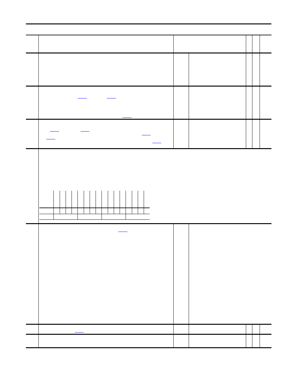
Drive OL Status
Indicates the status of various overload (OL) conditions.
• Bit 0 “NTC Shorted” indicates the Negative Temperature Coefficient (NTC) device has a short circuit.
• Bit 1 “NTC Open” indicates the NTC has an open circuit.
• Bit 2 “HS OverTemp” indicates heatsink temperature is above 105 °C for ratings 1.1…11.0 A, 115 °C for 14…34 A, 100 °C for 40…52 A.
• Bit 3 “HS Pending” indicates heatsink temperature is above 95C for ratings 1.1…11 A, 105 °C for 14…34 A, 90 °C for 40…52 A.
• Bit 4 “IT Trip” indicates the drive has exceed the 3 second rating of either the 150% normal duty rating or 200% of the heavy duty rating.
• Bit 5 “IT Pending” indicates the drive OL integrator is at 50% of the time out time.
• Bit 6 “IT Foldback” indicates the drive closed loop current limit is in a fold back condition. The value of the fold back is proportional to the calculated junction temperature.
• Bit 7 “Jnc Over Temp” indicates the junction temperature has exceeded the maximum temperature for the power semiconductor device.
347
Drive OL TP Sel
Enter or write a value to select the drive overload data displayed in
[Drive OL TP Data].
Note: Value 44 “HH PwrBdTemp” was added for firmware version 2.004. Added values 45 “IGBT CndLoss”, 46 “IGBT
SwtLoss” and 47 “Fwd CndLoss” for firmware version 3.003.
Default:
Options:
0 =
0 =
1 =
2 =
3 =
4 =
5 =
6 =
7 =
8 =
9 =
10 =
11 =
12 =
13 =
14 =
15 =
16 =
17 =
18 =
19 =
20 =
21 =
22 =
23 =
“Zero”
“Zero”
24 = “fIgbtWatts”
“fAbsIsCurr”
25 = “iIgbtPerMod”
“fDelta”
26 = “fFdThres”
“fAbsIqCurr”
27 = “fFdSlope”
“fOL_l”
28 = “fFdJunCase”
“fOL_m”
29 = “fFdWatts”
“fOL_k”
30 = “fMaxHsDegc”
“fOL_g”
31 = “fCsImp”
“fOL_intg”
32 = “fCsFltr”
“fCL_intg”
33 = “fPwmHz”
“fInvOLClim”
34 = “fElecHz”
“fJuncDegc”
35 = “fModIdex”
“fJunTmprMax”
36 = “fBoost”
“f60sPUCur”
37 = “fTotalWatts”
“f60sAmp”
38 = “fHSDegc”
“f3sPUCur”
39 = “iAdconv”
“f3sAmp”
40 = “Jct Temp”
“fRatioInvMtr”
41 = “Jct Tmp HiHp”
“fRatioMtrInv”
42 = “Jct Tmp Fwd“
“iConvertStat”
43 = ”HH Loss Intg”
“fIgbtThres”
44 = “HH PwrBdTemp”
“fIgbtSlope”
45 = “IGBT CndLoss”
“fIgbtEnergy”
46 = “IGBT SwtLoss”
“fIgbtJuncase”
47 = “Fwd CndLoss”
348
Drive OL TP Data
Displays the value selected by
[Drive OL TP Sel].
Default:
Min/Max:
0.0000
-/+2200000000.0000
RO
Real
350
Iq Actual Ref
Displays the value of motor current reference that is present at the output of the divide by flux calculation.
Default:
Min/Max:
Units:
0.0000
-/+8.0000 P.U.
P.U.
RO
Real
No.
Name
Description
Values
Link
able
Re
ad
-Write
Da
ta
T
yp
e
Options
Re
se
rv
ed
Re
se
rv
ed
Re
se
rv
ed
Re
se
rv
ed
Re
se
rv
ed
Re
se
rv
ed
Re
se
rv
ed
Re
se
rv
ed
Jnc
O
ver
Te
mp
IT F
oldback
IT P
ending
IT T
rip
HS P
ending
HS O
ve
rT
emp
NT
C Open
NT
C Shor
te
d
Default
x
x
x
x
x
x
x
x
0
0
0
0
0
0
0
0
Bit
15 14 13 12 11 10 9
8
7
6
5
4
3
2
1
0
0 = False
1 = True