Par 172, Par 173, Par 174 – Rockwell Automation 20D PowerFlex 700S AC Drives with Phase II Control Programming Manual User Manual
Page 46: Par 175, Par 176, Par 171, D in, Par 164
46
Rockwell Automation Publication 20D-PM001C-EN-P - July 2013
Chapter 2
Programming and Parameters
164
StopOper TP Data
Displays the data selected by
[Stop Oper TP Sel].
Default:
Min/Max:
0
-/+2147483648
RO
32-bit
Integer
165
Tune Test Status
Indicates which test (if any) is in progress.
• Value 7 is retained and is used to continue the Auto Tune test from the last point at which it was stopped.
Notes: Value 5 was changed to “Reserved” for firmware version 2.004. Value 7 “Mtr+Sys J” was changed to “Slip
Test” for firmware version 3.001. Value 8 “Find Home” was added for firmware version 3.003.
Default:
Options:
0 =
0 =
1 =
2 =
3 =
4 =
“None”
“None”
5 = “Reserved”
“MC Autotune”
6 = “Sys Inertia”
“Power Diag”
7 = “Slip Test”
“Motor Direct”
8 = “Find Home”
“PM Offset”
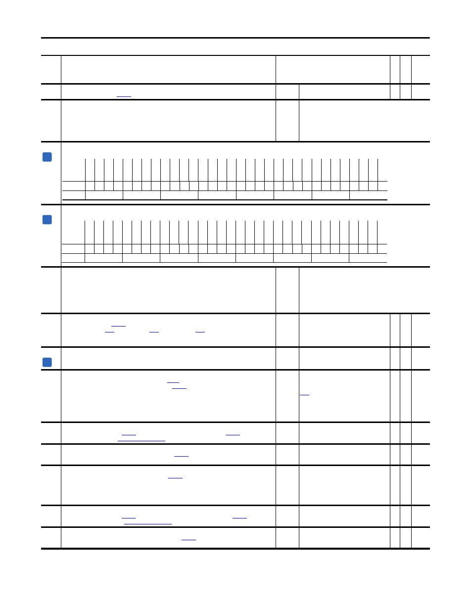
166 Motor
Ctrl
Cmmd
Displays the command bits to the Motor Control Processor from the Velocity Processor.
167 Motor
Ctrl
Ackn
Displays the Motor Control Processor's acknowledgment to the Velocity Processor for the Motor Control Command bits.
168
Normal Stop Mode
Sets the method of stopping the drive when a stop command is given. Normal Stop command and the RUN input
changing from true to false will command a Normal Stop.
Ramp Stop = decelerates to zero speed at the decal rate
CurLim Stop = Max torque / current applied until zero speed
Coast Stop = power removed from motor, motor coasts to zero
Default:
Options:
0 =
0 =
1 =
2 =
“Ramp Stop”
“Ramp Stop”
“CurLim Stop”
“Coast Stop”
169
SrLss ZeroSpdLim
Functionally equivalent to
[Zero Speed Lim], but is used exclusively in Sensorless speed mode. The value is
automatically set from
[Motor NP Hertz],
[Motor Poles]. The automatic setting
corresponds to the rated slip speed of the motor (synchronous speed - nameplate speed). The value can be
manually set.
Default:
Min/Max:
Units:
49.9975
0.0000/875.0000
rpm
Y
RW Real
170 Flying
StartGain
This parameter is currently not used.
Note: This parameter was added for firmware version 2.003.
Default:
Min/Max:
4000
0/32767
RW 16-bit
Integer
171
Set Speed Lim
Creates a tolerance - hysteresis band around the value in
[Limited Spd Ref] for comparison to average speed
feedback. The comparison controls bit 14 “At Setpt Spd” of
[Logic Status]. In general bit 14 “At Setpt Spd”
turns on when the feedback is within the tolerance of the reference.
• Turn-on level for rising feedback = Limited Spd Ref - Limit.
• Turn-off level for rising feedback = Limited Spd Ref + 2(Limit).
• Turn-on level for falling feedback = Limited Spd Ref + Limit.
• Turn-off level for falling feedback = Limited Spd Ref - 2(Limit).
Default:
Min/Max:
Units:
Scale:
17.6400
0.0000/882.0000
rpm
[Motor NP RPM] = 1.0 P.U.
Y
RW Real
172
Setpt 1 Data
Provides data for comparison to
[Setpt1 TripPoint], driving bit 16 “At Setpt 1” of
[Logic Status]. For
more information, please see
Default:
Min/Max:
Units:
0.0000
-/+8.0000 P.U.
P.U.
Y
RW Real
173
Setpt1 TripPoint
Provides the midpoint for operation of bit 16 “At Setpt 1” of
[Logic Status].
Default:
Min/Max:
Units:
0.1000
-/+8.0000 P.U.
P.U.
Y
RW Real
174
Setpt 1 Limit
Creates a tolerance - hysteresis band around the value in
[Setpt1 TripPoint].
• Turn-on level for ascending data = TripPoint - Limit.
• Turn-off level for ascending data = TripPoint + 2(Limit).
• Turn-on level for descending data = TripPoint + Limit.
• Turn-off level for descending data = TripPoint - 2(Limit).
Default:
Min/Max:
Units:
0.0100
0.0000/0.5000
P.U.
Y
RW Real
175
Setpt 2 Data
Provides data for comparison to
[Setpt2 TripPoint], driving bit 17 “Above Setpt 2” of
[Logic Status].
For more information, please see
.
Default:
Min/Max:
Units:
0.0000
-/+8.0000 P.U.
P.U.
Y
RW Real
176
Setpt2 TripPoint
Provides the midpoint for operation of bit 17 “Above Setpt 2” of
[Logic Status].
Default:
Min/Max:
Units:
0.2000
-/+8.0000 P.U.
P.U.
Y
RW Real
No.
Name
Description
Values
Link
able
Re
ad
-Write
Da
ta
T
yp
e
A
Options
Re
se
rv
ed
Re
se
rv
ed
Re
se
rv
ed
Re
se
rv
ed
Re
se
rv
ed
Re
se
rv
ed
Re
se
rv
ed
Re
se
rv
ed
Re
se
rv
ed
Re
se
rv
ed
Re
se
rv
ed
Re
se
rv
ed
Re
se
rv
ed
Re
se
rv
ed
Re
se
rv
ed
Re
se
rv
ed
Fa
ul
t R
es
et
Re
se
rv
ed
Re
se
rv
ed
Re
se
rv
ed
Re
se
rv
ed
Re
se
rv
ed
Re
se
rv
ed
Re
se
rv
ed
Re
se
rv
ed
Re
se
rv
ed
Bas
e B
loc
k
Re
se
rv
ed
Re
se
rv
ed
To
rq
ue
R
un
Flu
x R
un
CP E
nable
Default
x
x
x
x
x
x
x
x
x
x
x
x
x
x
x
x
0
x
x
x
x
x
x
x
x
0
0
0
0
0
0
0
Bit
31 30 29 28 27 26 25 24 23 22 21 20 19 18 17 16 15 14 13 12 11 10 9
8
7
6
5
4
3
2
1
0
0 = False
1 = True
A
Options
Re
se
rv
ed
Re
se
rv
ed
Re
se
rv
ed
Re
se
rv
ed
Re
se
rv
ed
Re
se
rv
ed
Re
se
rv
ed
Re
se
rv
ed
Re
se
rv
ed
Re
se
rv
ed
Re
se
rv
ed
Re
se
rv
ed
Re
se
rv
ed
Re
se
rv
ed
Re
se
rv
ed
Re
se
rv
ed
Fa
ul
t R
es
et
Re
se
rv
ed
Re
se
rv
ed
Re
se
rv
ed
Re
se
rv
ed
Re
se
rv
ed
Re
se
rv
ed
Re
se
rv
ed
Re
se
rv
ed
Re
se
rv
ed
Re
se
rv
ed
Po
w
er
D
ia
g
Pre
ch
ar
ge
To
rq
ue
R
un
Flu
x R
un
CP En
able
Default
x
x
x
x
x
x
x
x
x
x
x
x
x
x
x
x
0
x
x
x
x
x
x
x
x
x
x
0
0
0
0
0
Bit
31 30 29 28 27 26 25 24 23 22 21 20 19 18 17 16 15 14 13 12 11 10 9
8
7
6
5
4
3
2
1
0
0 = False
1 = True
A