Rockwell Automation 20D PowerFlex 700S AC Drives with Phase II Control Programming Manual User Manual
Page 147
Rockwell Automation Publication 20D-PM001C-EN-P - July 2013
147
Troubleshooting
Chapter 3
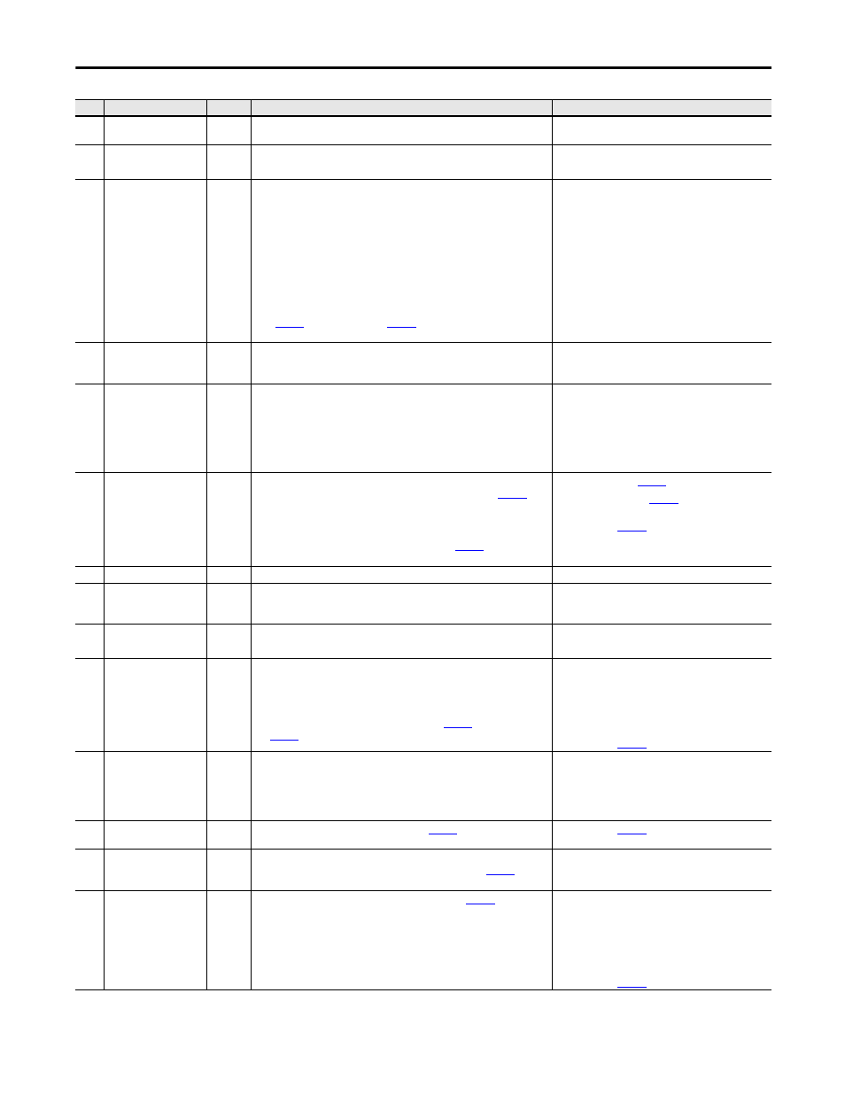
26
Ground Fault
1
A current to earth exceeds 35% of the peak drive rating.
Check the motor and external wiring to the drive output
terminals for a grounded condition.
27
Inst Overcurrent
1
The instantaneous motor current exceeds 214% of the rating.
• Reduce the mechanical load.
• Check the motor and external wiring to the motor.
28
VPL/MC Comm Fail
1
A communication failure has occurred between the Velocity Position Loop
(VPL) processor and the Motor Control (MC) processor on the main control
board. Possible cause are:
• The VPL is flashing the MC firmware into the MC processor when HIM
indicates “Loading Config”.
• The MC has failed to complete or pass diagnostic tests.
• The MC has not detected VPL handshake activity for over 32 ms.
• The VPL has not detected MC handshake activity for over 32 ms. This is
indicated when Fault Test Point 15 or 16 equals 1. This test point is viewed
in
[Fault TP select] is set to value 15
or 16.
• Cycle power to the drive.
• Reflash the firmware.
• Replace the Main Control board.
29
PWM Signal Short
1
This fault is detected when ever the actual IGBT gate is different than the
commanded IGBT states. This fault is detected by the Motor Control (MC)
processor.
30
MC Firmware
1
One of the following Motor Control (MC) firmware errors has occurred:
• MC Task Over Run
• Illegal Interrupt
• Self Diagnostic Fault
• Data Error
• Cycle power to the drive.
• Reflash the firmware.
• Replace the Main Control board.
31
Precharge Error
2
The precharge function has failed to complete within 30 seconds (default) of
the precharge request. The precharge time out is configurable in
[PreChrg TimeOut].
A precharge request is initiated when the DC Bus voltage is above the
Undervoltage Trip level and the precharge input is high (the requirement for
the precharge being high can be bypassed by setting
[PreChrg
Control], bit 01 “PreChrg Enable” to 0 “Off”).
• Verify the value in
[PreChrg TimeOut].
• Verify the bit value in
[PreChrg Control] = 1
“Enbl PrChrg”.
[PreChrg Err Cnfg]
32
PWM Asynch
1
The Motor Control Processor is not synchronized with SynchLink.
33
+/- 15volt Power
1
The12V DC control voltage is outside the tolerance range. The positive voltage
power must be within the band from +17.00 to +11.61V DC. The negative
voltage power must be within the band from -17.00 to -11.61V DC.
Replace switch mode power supply. For smaller frames,
replace drive.
35
Parameter Chksum
1
The checksum read from the EEPROM does not match the checksum calculated • Cycle power to the drive.
• Replace the Main Control board.
38
Brake OL Trip
2
The calculated temperature of the dynamic braking resistor is too high. The
temperature is calculated by a thermal model.
If the resistor is internal, the model uses the resistor characteristics stored in
the power structure EEPROM memory.
If the resistor is external, the model uses values of
[Brake PulWatts]
[Brake Watts].
Verify actual temperature of brake:
• If hot, wait for the brake to cool.
• If cold, cycle power to the drive. If cold, verify that the
values of Par 416 [Brake PulWatts] and Par 417
[Brake Watts] are correct.
[Brake OL Cnfg].
39
PowerEE CRC Fail
1
The Cycling Ring Checksum (CRC) of the data stored in the Power Board
EEPROM does not match the stored CRC.
Cycle power to the drive.
In frame 9…14 drives, check the communication bus
lines - 10 pin connector on the Main Control board, Fiber
Optic Power Interface board, and fiber optic cable
connections.
40
SLink Mult Oflow
2
A SynchLink Multiplier Overflow has occurred.
[SL Mult State] displays
SynchLink multiplier overflow errors.
[SL MultErr Cnfg].
41
Ridethru Timeout
1
The drive has been in a bus loss ridethrough condition for more than two
seconds (default). The ridethrough timeout is configurable in
[Power
Loss Time].
• Verify the AC Line.
• Verify the value in Par 407 [Power Loss Time].
42
DC Bus Undervolt
2
The Bus voltage has fallen below the level configured in
[Line
Undervolts].
Verify the AC Line.
In frames 1…4 and 9…14, verify that the precharge
resistor is present (with power off, there should be a
resistance between DC+ and BR+).
In frames 5 & 6, check the precharge board for errors. See
the precharge board LED for fault sequence.
Configured with
[BusUndervoltCnfg].
No.
Name
Type
(1)
Description
Action