Cable specification – MTS FlexTest Models 200 User Manual
Page 94
MTS FlexTest® Models 40/60/100/200 Controller Hardware
Model 494.44 Two-Station System Board
FlexTest Controller Configurations
94
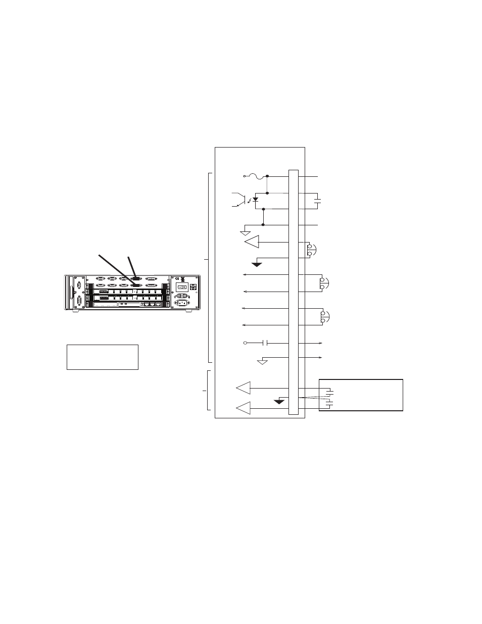
J29 A/B Load Frame Connections for the Model 494.44 System Board
Connector J29 A/B Load Frame provides interfaces to connect up to two load
frames and optional UPS (J29A only).
Cable specification
To maintain EMC compliance, the J29 A/B Load Frame cable must comply
with the following specifications:
Connector type–15-pin, type D, male EMI connector.
Backshell–EMI metallized plastic or metal.
Cable–18 AWG 8-conductor with foil shield, with the drain wire connected to a
metallized plastic backshell at the chassis.
HPU E Stop 2**
To HPU E Stop Chain
Controller Interlock
Open = Controller Interlock
494.44 System Board
Fused 24 V DC
to Crosshead
J29 A/B
L Frame
1
4
3
2
7
5
8
13
11
15
12
14
9
6
10
Crosshead Interlock
Common
+24V
External Program
Interlock Source
Open=Program Interlock
HPU E Stop 1
+24V
HSM High
Crosshead Unlock Power
Crosshead Unlock
Power Common
Load Frame
J29A J29B
Power
100-240 VAC
50-60 Hz, 1-2 A
DA Output
J24
1 2 3 4 5 6 7 8
1 2 3 4 5 6 7 8
LAN 2
LAN 1
DEBUG
MOT
OROLA
10/100 BASE T 10/100 BASE T
SCSI
BUSY
PIB
BUSY
PCI MEZZANINE CARD
PCI MEZZANINE CARD
J55 Dig Out
Dig In J54
J43A
J43B
J49
Aux Pwr
Estop/Run J23
Interlock
J29A
J29B
Load Frame
J28 HSM
A-B
HPU J25
UPS AC Fail*
UPS
Open=Logic1=Active
Open=Logic1=Active
UPS Battery Low*
* UPS Inputs
are only available
on connector J29A
Load
Frame
Note: A custom Y Cable
(PN 100-197-651) is
required for UPS systems.
To HPU E Stop Chain
** MTS Model 505 Pumps and older
do not use the HPU E-Stop 2 signal.