Cable specification – MTS FlexTest Models 200 User Manual
Page 100
MTS FlexTest® Models 40/60/100/200 Controller Hardware
Model 494.44 Two-Station System Board
FlexTest Controller Configurations
100
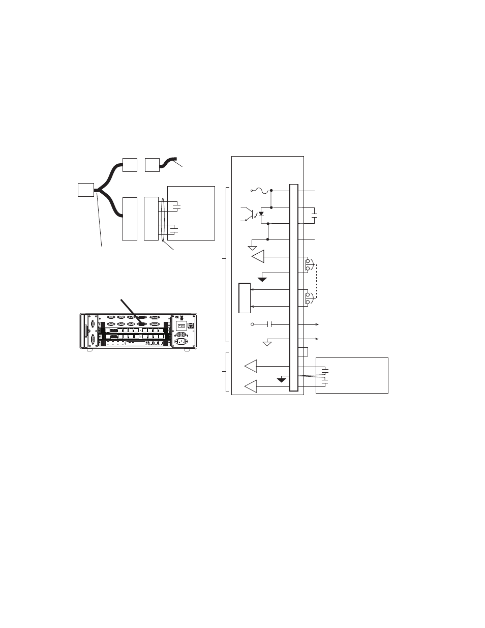
UPS Connections for the Model 494.44 System Board (FT40)
The following drawing shows UPS connections for the Model 494.44 System
Board. Once connected, you must use your controller software to configure the
various UPS options.
Cable specification
To maintain EMC compliance, the UPS cable that connects to the load frame Y
cable must comply with the following specifications:
Connector type–9-pin, type D, male EMI connector.
Backshell–EMI metallized plastic or metal.
Cable–26–22 AWG, four-conductor with overall braided shield, with the braided
shield connected to the metallized backshell at the chassis.
Controller Interlock
Open = Controller Interlock
494.44 System
I/O Board
Fused 24 V DC
to Crosshead
J29A
L Frame
1
4
3
2
7
5
8
13
12
14
11
15
9
6
10
Crosshead Interlock
Common
+24V
External Program
Interlock Source
Open=Program Interlock
To J25 HPU
J25
HPU
6
5
HPU E Stop
+24V
HSM High
Crosshead Unlock Power
Crosshead Unlock
Power Common
Load Frame
J29A
Reserved
Power
100-240 VAC
50-60 Hz, 1-2 A
DA Output
J24
1 2 3 4 5 6 7 8
1 2 3 4 5 6 7 8
LAN 2
LAN 1
DEBUG
MOT
OROLA
10/100 BASE T 10/100 BASE T
SCSI
BUSY
PIB
BUSY
PCI MEZZANINE CARD
PCI MEZZANINE CARD
J55 Dig Out
Dig In J54
J43A
J43B
J49
Aux Pwr
Estop/Run J23
Interlock
J29A
J29B
Load Frame
J28 HSM
A
-B
HPU J25
UPS AC Fail*
UPS
UPS
AC Fail
Active Alarm:
Open=Logic1
UPS Battery Low*
* UPS Inputs
are only available
on connector J29A
Load
Frame
UPS
To
494.44
J29A
Custom J29 Y Cable
(PN 100-197-651)
required for UPS systems.
D9S
2
7
8
4
D9P
2
7
8
4
D15S
UPS
Battery Low
D15P
UPS Cable
Load
Frame
Cable
D15P