Cable specification – MTS FlexTest Models 200 User Manual
Page 245
Model 493.73 HPU Interface Board
MTS FlexTest® Models 40/60/100/200 Controller Hardware
Digital I/O and Transition Boards
245
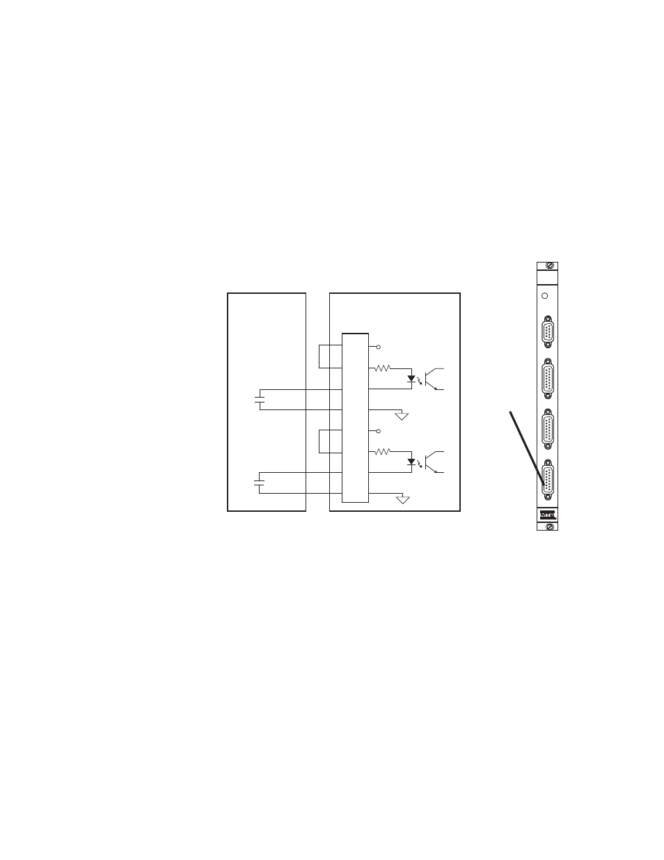
UPS Connections for the Model 493.73 HPU Board (FT60, FT100, FT200, FTGT)
The following drawing shows UPS connections for the Model 493.73 HPU
board. Once connected, use your controller software to add UPS hardware
resources and configure the various UPS options.
Note
Systems that use Series 793 Control Software have Hwi Editor and
station setup settings for UPS systems.
Cable specification
To maintain EMC compliance, J54 SYS DI/O cables must comply with the
following specifications:
Connector–15-contact, type D male EMI connector.
Backshell–metallized plastic or metal.
Cable—26 to 22 AWG, 4-conductor with overall braided shield, with the
braided shield connected to the backshell at the chassis.
+24 V DC
+24 V DC
493.73 HPU Board
J54 SYS DI/O
UPS
SERVICE
493.73
HPU
J23
E-STOP OUT
J24
E-STOP IN
J25 HPU
J54
SYS D I/O
493.73
HPU Board
AC Fail
Contacts
Open = Logic 0
1
2
3
4
5
6
7
8
J54
SYS DI/O
Digital Input 1
Low Battery
Contacts
Open = Logic 0
Digital Input 2