Cable specification, 41 system board, J55 digital output – MTS FlexTest Models 200 User Manual
Page 64
MTS FlexTest® Models 40/60/100/200 Controller Hardware
Model 494.41 Single-Station System Board
FlexTest Controller Configurations
64
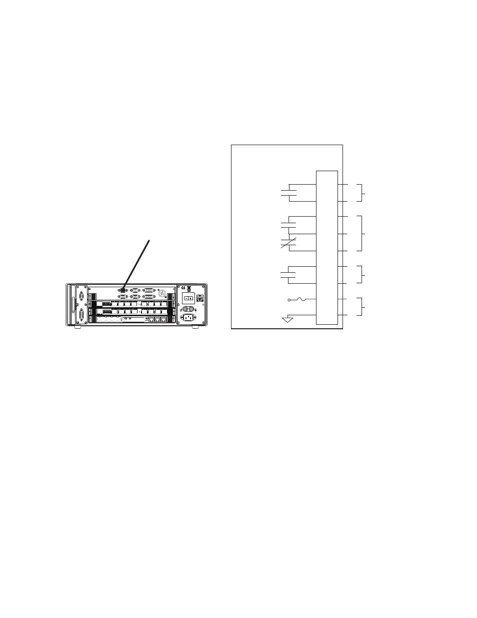
J55 Digital Output Connections for the Model 494.41 System Board
Connector J55 Dig Out provides three general-purpose digital outputs that can
send digital-logic signals to external switches or logic devices.
Cable specification
To maintain EMC compliance, the J55 Digital Output cable must comply with
the following specifications:
Connector–9-pin, type D, male EMI connector.
Back shell–EMI metallized plastic.
Cable–AWG and number of conductors as required. Braided shield with the
shield connected to the metallized backshell at the chassis.
Relay Contact
Relay Contact
Relay Contact
494.41 System Board
Power
100-240 VAC
50-60 Hz, 1-2 A
DA Output
J24
1 2 3 4 5 6 7 8
1 2 3 4 5 6 7 8
J54 Dig In
J49
Aux Pwr
J25 Hpu
Dig Out J55
Intlk J43
E-stop J29
J28 HSM
LAN 2
LAN 1
DEBUG
MOT
OROLA
10/100 BASE T 10/100 BASE T
SCSI
BUSY
PIB
BUSY
PCI MEZZANINE CARD
PCI MEZZANINE CARD
J55
1
2
3
4
5
6
7
8
9
Output 1
Output 3
+24 V
Output 2
Aux Power
J55 Digital Output