Transition boards, Transition bus (rear) – MTS FlexTest Models 200 User Manual
Page 109
FlexTest 200 Controller Configuration
MTS FlexTest® Models 40/60/100/200 Controller Hardware
FlexTest Controller Configurations
109
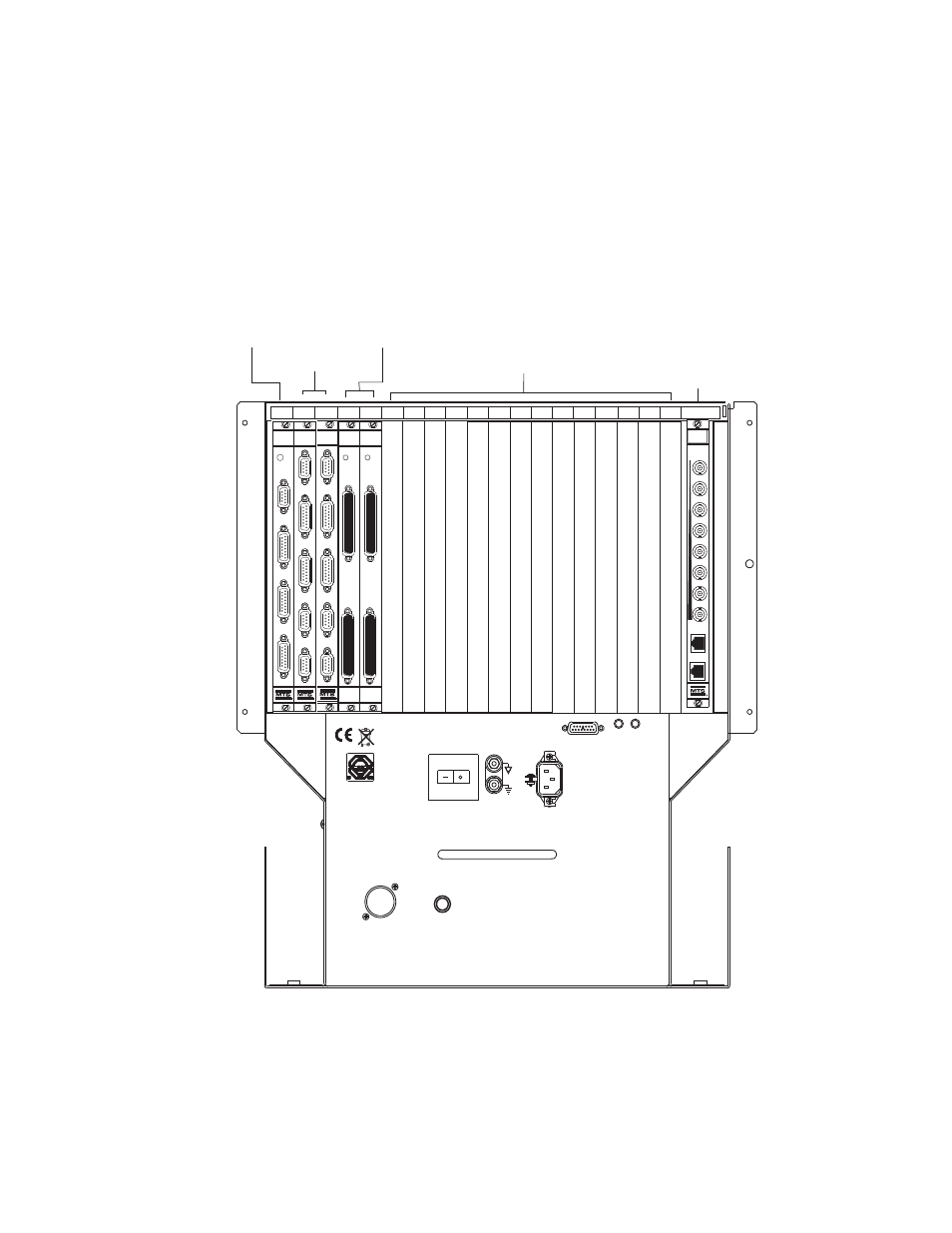
Transition boards
The Model 494.20 Chassis houses up to 20 transition boards in its rear card cage.
The physical board locations must match the board locations defined in your
hardware-mapping software.
Note
Series 793 Software maps HSM interlock I/O connectors (J3 A/B on
494.74, J43 A/B on 493.74) to stations on a left-to-right basis.
Transition Bus (Rear)
100-240 VAC
50-60 Hz, 16-10A
Over
Temp
Power
OK
J39 Power Monitor
Power
24 V DC Output
Fuse 250V
15A Fast
24 V
DC Output
493.73 HPU
Board
Unpowered Slot
BNC Boards
494.75 Input or
494.76 Output
HSM
Boards
494.74 (1 slot)
or 493.74 (2 slot)
Spare
Slots
Digital I/O
493.72
1
2
3
4
SERVICE
493.73
HPU
J23
E-STOP OUT
J24
E-STOP IN
J25 HPU
J54
SYS D I/O
J49 AUX PWR
J3A STA
J3B STA
J28A HSM
J28B HSM
494.74
HSM
+ 12 V
493.72
D I/O
J3 IN
J4 OUT
5
6
7
8
9
10
11
12
13
14
15
16
17
18
19
J49 AUX PWR
J3A STA
J3B STA
J28A HSM
J28B HSM
494.74
HSM
+ 12 V
493.72
D I/O
J3 IN
J4 OUT
First
494.76
ANALOG
OUTPUT
CH 1 - 8
Last
J11
J12
A
1-2
3-4