Cable specification, Jumper plug required, 41 system board – MTS FlexTest Models 200 User Manual
Page 61: J43 interlock
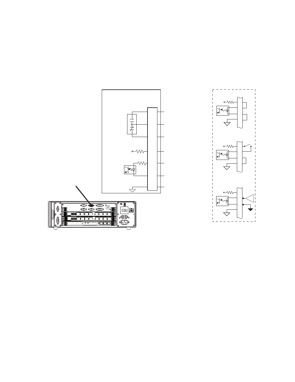
Model 494.41 Single-Station System Board
MTS FlexTest® Models 40/60/100/200 Controller Hardware
FlexTest Controller Configurations
61
J43 Interlock Connections for the Model 494.41 System Board
Connector J43 Interlock provides one optically isolated interlock input and a
relay-contact interlock output.
Cable specification
To maintain EMC compliance, the J43 Interlock cable must comply with the
following specifications:
Connector type–9-pin, type D, male EMI connector.
Backshell–EMI metallized plastic or metal.
Cable–shielded twisted pairs (24 AWG minimum), braided shield with the shield
connected to the metallized backshell at the chassis.
Jumper plug required
If connector J43 is not used, you must install a jumper plug to maintain the
integrity of the interlocks. Use jumper plug part number 100-057-245, or jumper
pins 1-2, 3-4, and 5-9.
+24V
1
2
3
4
Interlock Disabled
+24V
1
2
3
4
Switch Contact
(Open = Interlock)
+24V
1
2
3
4
Logic Input
(0=Interlock)
Interlock In (Gnd)
Interlock Out (NO)
Interlock = Open
Interlock Out (NC)
Interlock = Closed
Common
- Interlock In
+ Interlock In
Interlock In (Pwr)
+24V
J43
Intlk
494.41 System Board
6
7
8
1
2
3
4
Interlock
Output
Interlock
Input
Power
100-240 VAC
50-60 Hz, 1-2 A
DA Output
J24
1 2 3 4 5 6 7 8
1 2 3 4 5 6 7 8
J54 Dig In
J49
Aux Pwr
J25 Hpu
Dig Out J55
Intlk J43
E-stop J29
J28 HSM
LAN 2
LAN 1
DEBUG
MOT
O
ROLA
10/100 BASE T 10/100 BASE T
SCSI
BUSY
PIB
BUSY
PCI MEZZANINE CARD
PCI MEZZANINE CARD
J43 Interlock