For more information, Input power, Output power – MTS FlexTest Models 200 User Manual
Page 236
MTS FlexTest® Models 40/60/100/200 Controller Hardware
Model 494.33 Digital I/O Power Supply
Digital I/O and Transition Boards
236
Power Connections
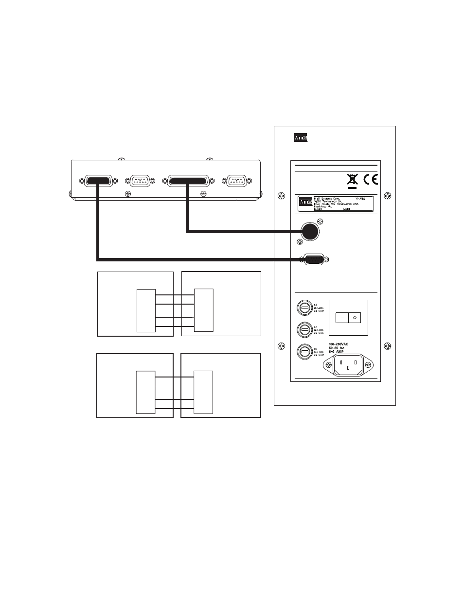
Model 494.32 DI/O
Breakout Box
Input and output channels are grouped into banks that are independently
powered.
For more information
For more information on the Model 494.32 DI/O Breakout Box, see
494.32 8-Channel DI/O Breakout Box”
494.32 DI/O Breakout Box
J19 Input Power
J29 Output Power
494.32 DI/O Breakout Box
494.33 DI/O Pwr Supply
J3 Input Pwr
2
6
4
8
Input Bank 1
(Power 1)
Inputs 1-4
Input Bank 2
(Power 2)
Inputs 5-8
+ 24 V DC
- 24 V DC
+ 24 V DC
- 24 V DC
J1 Output Pwr
A
C
B
D
Output Bank 1
(Power 3)
Outputs 1-4
Output Bank 2
(Power 4)
Outputs 5-8
494.33 DI/O Pwr Supply
Input Power J19
Digital Inputs J10
Output Power J29
Digital Outputs J20
11
13
3
6
Input
Power
2
5
1
4
Output
Power
+ 24 V DC
- 24 V DC
+ 24 V DC
- 24 V DC
Model 494.32 DI/O Breakout Box
Model 494.33 DI/O Power Supply
Maximum Input Pwr current: 125 mA per input device (1 A total).
Maximum Output Pwr current: 1.75 A per output device (14 A total).
Maximum Cable Length: 6 m (20 ft)
J1 Output Pwr
J3 Input Pwr
Power Supply
494.33
DIO Remote Power Supply
F1 Output Pwr Power
F2 Output Pwr
F3 Input Pwr