J4a j4b – MTS FlexTest Models 200 User Manual
Page 125
Model 494.40 I/O Carrier Board
MTS FlexTest® Models 40/60/100/200 Controller Hardware
VME Bus Boards
125
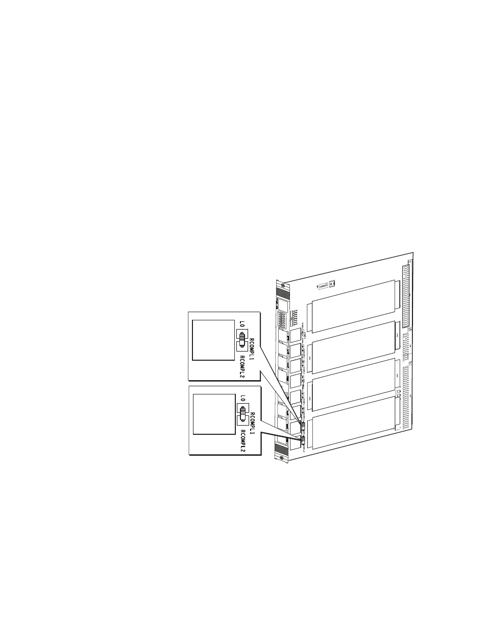
How to Install a Bridge-Completion Resistor on an I/O Carrier Board
You can install bridge-completion resistors on the I/O Carrier board for use with
DUC cards that condition 1/4-bridge transducers such as strain gages.
The I/O Carrier circuit board has eight sockets for bridge completion resistors.
Each resistor socket is associated with one of the eight RJ-50 connectors on the
front panel.
1. Determine the RJ-50 connector used by the DC conditioner.
2. On the I/O Carrier circuit board, install the bridge completion resistor in the
socket associated with that connector.
3. On the DUC card, set the bridge-completion switch to the quarter-bridge
position.
1
2
3
4
5
6
7
8
J1A
J1B
J2A
J2B
J3A
J3B
J4A
J4B
J4A
J4B